Einleitung
Around here it's all about gadget guts. With VR becoming all the rage, we couldn't wait for a little Vive-section. What does HTC have hiding right before your eyes? Strap a black box to your head, 'cause we're about to find out! It's time to tear down the Vive.
Looking for more virtual fun? Follow us on Instagram, Twitter, and Facebook for all the latest repair news.
Was du brauchst
Einführungsvideo
-
-
It's been a long time coming, but 2016 seems to be the year when virtual reality finally becomes an actual reality. How does it work? Well, here are the specs:
-
Two 1080p AMOLED displays with a combined resolution of 2160 x 1200
-
90 Hz refresh rate
-
Built-in front-facing camera and microphone
-
Accelerometer, gyroscope, and laser position sensor
-
360-degree headset tracking via Lighthouse IR emitters
-
110º horizontal field of view
-
-
-
After unplugging
ourselves from the Matrixthe four headset cables, we spy the headset's model number: 0PJT100. -
We also spot a standard 3.5 mm audio jack, DC barrel jack, and a single HDMI port flanked by two USB 3.0 ports.
-
Bottoms up! We flip the Vive and go eye-to-eye with the front-facing camera. This unblinking cyclops also provides AR for the Vive. What's it running on? Let's get inside and find out.
-
-
-
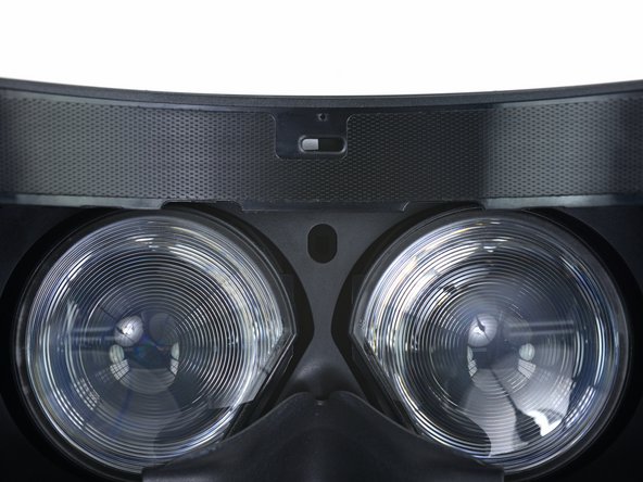
First to go is the interchangeable foam insert, velcroed to the headset for our convenience.
-
We peel back the velcro to reveal a hidden message.
-
Nestled in a nook between the eyepieces is a proximity sensor that detects when the Vive is actually on your face—presumably to shut off the displays, conserving power and processor resources.
-
-
-
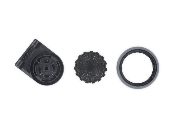
Cog-zooks! We've got our gears turning as we remove the eye relief adjustment on the Vive headset.
-
The Rift CV1 doesn't have this feature, probably because its asymmetric lenses allow you to adjust focus by simply pushing the headset higher or lower on your face. Is this confirmation of a different approach to optics in the Vive? Only more teardown will tell.
-
-
-
We can't help but experience a little déjà vu as we unmask our latest subject.
-
Pulling back the outer shell on the Vive reveals a number of sensors—32 in total, according to HTC.
-
These photodiodes take in IR light from the two Lighthouse base stations as they flash and sweep light across the room. This enables a connected PC to calculate the headset's position and orientation in space as a function of the time between receiving the flash and the following IR laser sweep.
-
-
-
A closer look at the outer shell reveals that each divot on the surface holds a small IR filter.
-
These IR windows give the photodiodes beneath a clear view of the lights and lasers emitted from the Lighthouse base stations.
-
-
-
With the outer sheath removed, we flip the switch on a few ZIF connectors to disconnect the IR photodiode webbing from the motherboard.
-
After deftly dispatching a hidden press connector behind the front-facing camera, the whole sensor array lifts off. Easy peasy.
-
Hiding in the back of the assembly, we find a couple spring contacts that deliver power to the whole setup—and behind that swath of copper tape, the camera.
-
-
-
With tweezers in hand, we pluck the front-facing camera out of the Vive. Manufactured by Sunny Optical Technology, it reads: TG07B C1551
-
Working our way around the sensor net, we note that each of the sensors is individually numbered (photodiodes 18 and 19 in the photo).
-
-
-
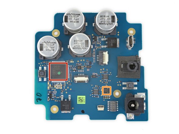
We have liftoff—of the motherboard, that is. Let's see what sort of silicon is lurking beneath those huge
heatEMI shields. On the front side of the board: -
STMicroelectronics STM32F072RBH6 32-Bit ARM Cortex-M0 Microcontroller
-
Toshiba TC358870XBG 4K HDMI to MIPI Dual-DSI Converter (Also found in Oculus Rift CV1)
-
SMSC USB5537B 7-Port USB Hub Controller
-
Alpha Imaging Technology AIT8328 SoC With Image Signal Processor
-
Cmedia CM108B USB Audio SoC
-
Micron M25P40 4 Mb Serial Flash Memory
-
Micron N25Q032A13ESE40E 32 Mb Serial Flash Memory
-
-
-
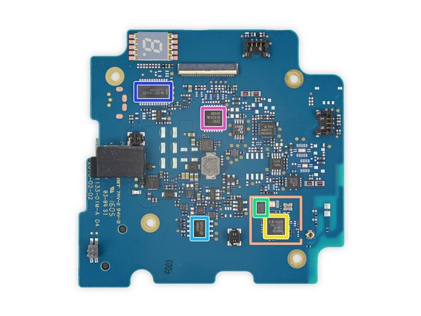
Even more chips on the front:
-
Texas Instruments TPS54341 Buck Converter
-
Texas Instruments TS3DV642 12-Channel Bi-Directional Multiplexer/Demultiplexer
-
Cirrus Logic WM5102 Audio Codec
-
Pericom Semiconductor PI3EQX7841 USB 3.0 Repeater
-
Lattice Semiconductor LP4K81 Ultra-low Power FPGA
-
Texas Instruments display power management (likely)
-
Texas Instruments TS3A5018 4-Channel SPDT analog switch
-
-
-
-
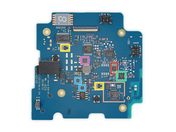
Even, even more chips on the front:
-
Texas Instruments OPA171 operational amplifier
-
Texas Instruments TXS0102 2-bit bidirectional voltage-level translator
-
Texas Instruments TXB0104 4-bit bidirectional voltage-level translator
-
Texas Instruments LM2682 voltage doubling inverter
-
Texas Instruments LM2665 voltage converter
-
Texas Instruments TPS62290 1 A step-down converter
-
Richtek RT5795A 2 A synchronous step-down converter
-
-
-
Bringing up the rear, we have:
-
Nordic Semiconductor nRF24LU1P 2.4 GHz SoC (x2)
-
NXP Semiconductors LPC11U35FBD48/401 ARM Cortex-M0 Microcontroller
-
Lattice Semiconductor ICE40HX8K-CB132 High-Performance FPGA
-
Invensense MPU-6500 6-axis Gyroscope and Accelerometer Combo
-
Micron N25Q032A13ESE40E 32 Mb Serial Flash Memory
-
Texas Instruments (formerly National Semiconductor) LP38798SD 800 mA Linear Voltage Regulator
-
ON Semiconductor NCP380HMUAJAATBG adjustable load switch
-
-
-
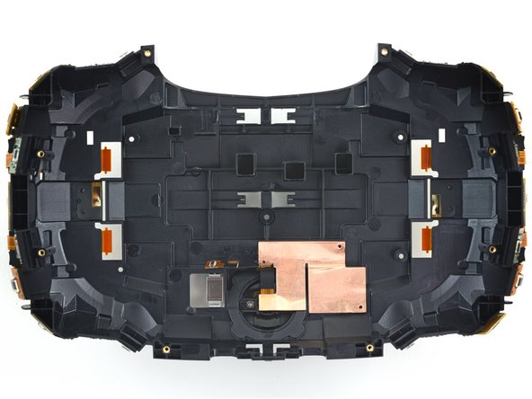
Next out: the midframe that housed the motherboard. Clinging to its side we find a small ribbon cable that plays host to the headset button.
-
A closer look at the midframe reveals a slot for the little black nub on the back of the left display panel.
-
Ready to go deeper, we remove the twin lens-and-display assemblies from their housing and peel off the rubber light-gasket from around the lenses.
-
-
-
Speaking of interpupillary distance adjustment, here's the mechanism that makes that possible.
-
It's a simple threaded rod with a slider at the top. It couldn't be simpler, really—just give it a twist.
-
-
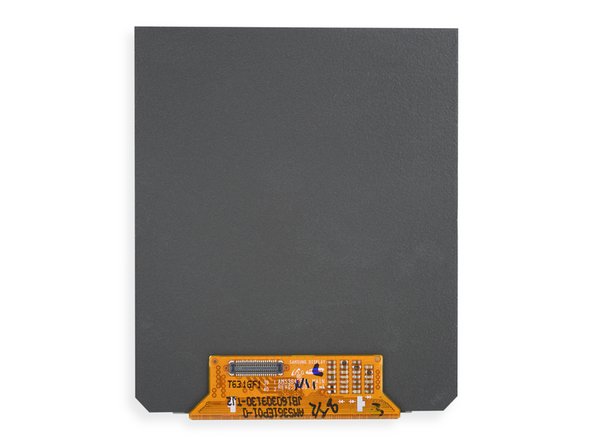
After adios-ing four Phillips screws and doing a little investigative prying, we lift away the display cover for access to one of the twin Samsung-branded AMOLED panels.
-
Each display measures ~91.8 mm diagonally, which translates to ~447 ppi. For comparison, the Rift CV1 has ~456 ppi due to a slightly smaller display (90 mm) that still packs the same resolution as the Vive.
-
-
-
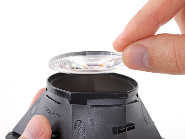
A bit of adhesive secures each lens, but it doesn't take much to pop them out.
-
We note a set of concentric rings in each lens—the familiar indicator of Fresnel lenses.
-
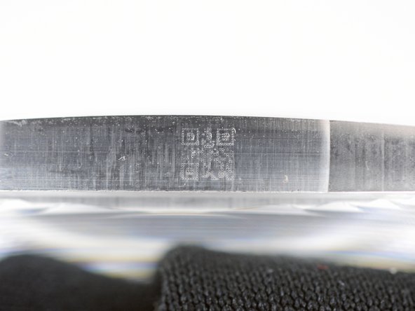
Etched right into the side of the lens, we find the smallest QR code we've ever seen. Despite our best efforts, we can't get it to scan.
-
-
-
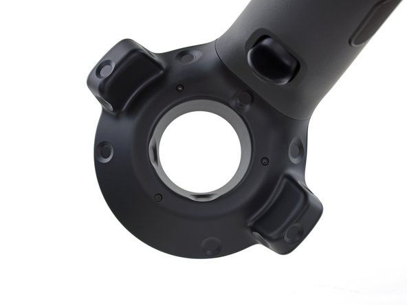
With the headset completely disassembled, it's time to move on to the controller. A quick inspection reveals the model number: 2PR7100.
-
The Vive is manufactured by HTC, but it's quite evident that Valve had plenty of input on the design process. The controller touchpad is very reminiscent of the ones we found on the Steam Controller.
-
In addition to the touchpad and buttons, the controller comes packed with 24 sensors (including two inside the ring!) that allow it to accurately track the its position based on the two Lighthouse base stations.
-
-
-
-
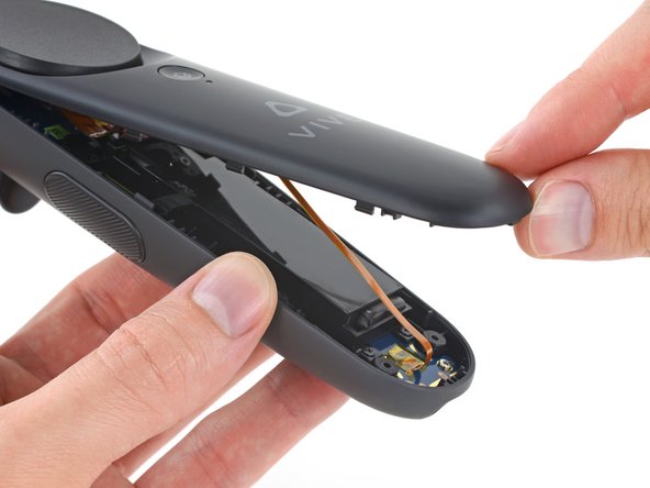
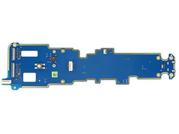
After removing the touchpad assembly from the controller, we immediately notice that the daughterboard is near-identical to the one found in the Steam Controller.
-
Just like before, the touchpad is driven by a Cirque 1CA027 companion MCU.
-
As with the Steam Controller, the PCB also features seven well-labeled test points that make it easy to directly interface with the board for testing.
-
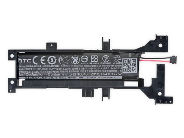
Up next is the 3.85 V, 3.69 Whr, and 960 mAh Li-poly battery. After giving it a good looksee, we spot the model number B0PLH100, and a large QR code.
-
-
-
There are a few common chips between the controller and the headset, as well as a few new ones:
-
NXP Semiconductors LPC11U37F 32-Bit ARM Cortex-M0 Microcontroller
-
Lattice Semiconductor ICE40HX8K-CB132 Ultra-low Power FPGA
-
Invensense MPU-6500 6-axis Gyroscope and Accelerometer Combo
-
Micron M25P40 4 Mb Serial Flash Memory
-
Texas Instruments (formerly National Semiconductor) LP38798SD 800 mA Linear Voltage Regulator
-
Texas Instruments BQ24158 Battery Charger IC
-
ON Semiconductor FSA3000 2-Port USB 2.0 Switch
-
-
-
Even more ICs in the controller:
-
Dialog Semiconductor (formerly Silego) SLG46110 Programmable Mixed Signal Matrix
-
Texas Instruments TCA6418E 18-Ch. GPIO Expander
-
ON Semiconductor NCP380HMUAJAATBG adjustable load switch
-
Richtek LDO Regulator (likely)
-
Richtek RT5795A 2 A synchronous step-down converter
-
Bluetooth Transceiver Circuitry
-
-
-
With the headset and controllers torn asunder, we move right along to one of the Lighthouse base stations. What secrets does it hold? Let's find out!
-
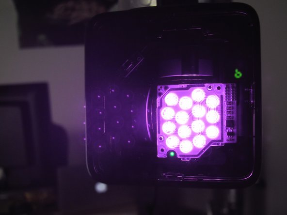
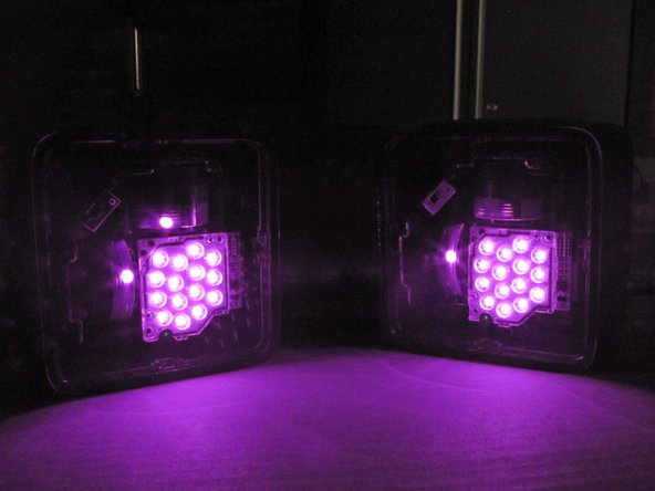
Firing up our IR camera, we get a glimpse of the internals through the IR-transparent front panel—an array of bright IR LEDs, and a pair of motorized lasers make the Lighthouse shine bright.
-
Each Lighthouse flashes its IR LED array, signaling the start of a cycle. Vertical and horizontal lasers then sweep across the room, and all of those fancy photosensors on the headset and controllers start looking for lasers.
-
The tracked headset or controller can then determine its position based on the order its sensors receive the laser sweeps.
-
-
-
Time to crack the Lighthouse open and check how the system matches our science.
-
The base station sports the model number 2PR8100 as well as a Class 1 Laser Product regulatory label.
-
With a trusty iOpener and opening pick in hand, we quickly dispatch a few clips and some sticky gasketing that secure the base station's front panel.
-
-
-
The front panel removed with relative ease, we prepare for the harrowing task of extracting the complex internals from this optical tech marvel.
-
Aaaand we're done. Lucky for us, the whole unit is installed as a single assembly within the Lighthouse base station housing. Just remove the four Torx screws, and it falls right out.
-
With the cover off, we get a look at the array of IR LEDs and spinning motor-mounted laser emitters, as well as a single IR photodiode that allows the device to sync up with its counterpart.
-
IC identification:
-
ON Semiconductor FAN3111E MOSFET Driver
-
MOSFET
-
-
-
Let's shed some light on what sort of chips are powering the Lighthouse:
-
NXP Semiconductors LPC11U37F 32-Bit ARM Cortex-M0 Microcontroller
-
Texas Instruments (formerly National Semiconductor) LP38798SD 800 mA Linear Voltage Regulator
-
Broadcom BCM20736 Bluetooth Smart SoC
-
Macronix MX25L1006E 1 Mb Serial Flash Memory
-
STMicroelectronics ST1480AC 12 Mbps RS-485/RS-422 Transceiver
-
Texas Instruments TLC59284 16-Channel LED Driver
-
Texas Instruments SN74AHCT595DBR 8-Bit Shift Register With 3-State Output Register
-
-
-
Lighthouse IC identification, continued:
-
STMicroelectronics LIS2DH12 3-Axis MEMS Accelerometer
-
Dialog Semiconductor (formerly Silego) SLG46120 Programmable Mixed Signal Array
-
Renesas (formerly Intersil) ISL58303 800 mA Triple Output Laser Diode Driver
-
Texas Instruments DRV10866 3-Phase BLDC Motor Driver
-
Analog Devices (formerly Linear Technology) LTC6904 Serial Port Programmable Oscillator
-
ON Semiconductor FSA3000 2-Port USB 2.0 Switch
-
ON Semiconductor NCP305LSQ30T 3.0 V Voltage Detector
-
-
-
More Lighthouse IC identification:
-
STMicroelectronics LMV358 Dual Operational Amplifier
-
STMicroelectronics LMV321 Single Rail-to-Rail Operational Amplifier
-
Diodes Incorporated AP331A Single Differential Comparator
-
Texas Instruments SN74LVC07A Hex Buffer/Driver
-
ON Semiconductor NCP380HMUAJAATBG Power Distribution Switch
-
Texas Instruments TPS22920 4 A / 3.6 V Load Switch
-
Texas Instruments LMR12020 2 A Step-Down Voltage Regulator
-
-
-
Even more Lighthouse IC identification:
-
Texas Instruments LP38798 800 mA LDO Regulator
-
Diodes Incorporated AP2127K-3.3TRG1 300 mA / 3.3 V LDO Regulator
-
-
-
All of our repair wishes are coming true today! Each laser motor mounts to the Lighthouse emitter assembly via four T5 Torx screws, and connects to the motherboard with a single ZIF connector.
-
Nidec may not be a household name, but we've seen their DC motors before powering fans in the Xbox One Kinect, as well as the Mac Pro Late 2013. These particular motors read: B2044N01.
-
With the Lighthouse parts laid out for inspection, this teardown is adjourned.
-
-
-
The HTC Vive Repairability Score: 8 out of 10 (10 is best):
-
Although it's a complicated bit of kit, the headset breaks down readily and without damage.
-
The head strap and face pads are removable and don't incorporate any sensors or electronics that might be prone to failure.
-
Standard Phillips and Torx screws are used throughout the headset, controllers, and base stations.
-
Reuse of the touchpad hardware from the Steam Controller means some replacement components are likely already available.
-
The large number of components, many of them quite delicate, means you'll want a service manual before attempting repairs.
-
Adhesive is used sparingly, but secures the lenses, Lighthouse base station covers, and sensor arrays.
-


79 Kommentare
It might be important to note that removing the face plates or even touching the motors breaks the factory calibration and will produce tracking errors in the future. Currently there is no way for the consumer to re-calibrate the sensors.
I'm hesitant to agree that merely exposing the sensors "breaks" tracking. I (very carefully) disassembled one of the controllers to re-seat a loose haptic motor and notice no difference in tracking accuracy or precision. The controller may be offset by some minute, imperceptible amount but it hasn't produced any problems. I think you would be fine attempting minor repairs with the appropriate amount of caution.
@ Michael Stinton, That's a controller... he's talking about the HMD itself.
This seems doubtful, as merely picking up the base stations causes the laser motors to visibly jiggle and rotate. At any rate, we reassembled our Vive after the teardown and it seems to be working fine. I can't swear there are no tracking errors as there were occasional glitches when we first unboxed it and there are occasional glitches now—but for whatever it's worth, I can't tell any difference.