Diese Version enthält möglicherweise inkorrekte Änderungen. Wechsle zur letzten geprüften Version.
Was du brauchst
-
Dieser Schritt ist noch nicht übersetzt. Hilf mit, ihn zu übersetzen!
-
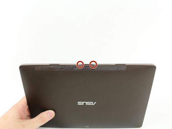
Use T5 Torx Screwdriver to remove two 4.5 millimeter T5 screws on either side of the port on the bottom of the tablet.
-
-
Dieser Schritt ist noch nicht übersetzt. Hilf mit, ihn zu übersetzen!
-
Use the Plastic Opening Tool to pry between the main tablet body and the outer rim casing. Remove the outer rim casing by prying all the way around the device and pulling the rim upward.
-
-
Dieser Schritt ist noch nicht übersetzt. Hilf mit, ihn zu übersetzen!
-
Remove the four 2 millimeter Phillips #00 screws at the corners of the tablet.
-
-
Dieser Schritt ist noch nicht übersetzt. Hilf mit, ihn zu übersetzen!
-
Use a Phillips #00 Screwdriver to remove the three 3 millimeter screws securing the front panel to the back panel found above the camera area, on the top portion of the tablet.
-
-
Dieser Schritt ist noch nicht übersetzt. Hilf mit, ihn zu übersetzen!
-
Use a Phillips #00 Screwdriver to remove the three 3 millimeter screws securing the front panel to the back panel found on the bottom portion of the tablet near the port.
-
-
Dieser Schritt ist noch nicht übersetzt. Hilf mit, ihn zu übersetzen!
-
Remove back panel by pulling away from the remaining device.
-
-
Dieser Schritt ist noch nicht übersetzt. Hilf mit, ihn zu übersetzen!
-
Use Phillips #00 Screwdriver to remove four 3 millimeter screws found on the metal panel.
-
-
Dieser Schritt ist noch nicht übersetzt. Hilf mit, ihn zu übersetzen!
-
Use Plastic Opening Tool to pry off the metal panel from the battery starting on the right side corners and working around the rest of the panel.
-
-
-
Dieser Schritt ist noch nicht übersetzt. Hilf mit, ihn zu übersetzen!
-
Peel off tape from around the edges of the battery.
-
Insert Plastic Opening Tool into slot on side of battery found near the wire bundle.
-
Lift up the battery off of the device.
-
-
Dieser Schritt ist noch nicht übersetzt. Hilf mit, ihn zu übersetzen!
-
Use a Phillips #00 Screwdriver to remove the six 3 millimeter screws securing the motherboard to the screen.
-
-
Dieser Schritt ist noch nicht übersetzt. Hilf mit, ihn zu übersetzen!
-
Detach the Wifi and GPS antennas (three coaxial cables connected to the motherboard) using hands,metal spudger, or tweezers by lifting away from the device.
-
-
Dieser Schritt ist noch nicht übersetzt. Hilf mit, ihn zu übersetzen!
-
Use fingers, plastic opening tool, or metal spudger to lift the clips to the ZIF connector. Remove the ribbon cables attached underneath.
-
-
Dieser Schritt ist noch nicht übersetzt. Hilf mit, ihn zu übersetzen!
-
Remove any tape that is holding down any free wires.
-
Carefully lift the motherboard and slide it out from underneath its constraints.
-
-
Dieser Schritt ist noch nicht übersetzt. Hilf mit, ihn zu übersetzen!
-
Unclip the ribbon cable from the ZIF connector using a plastic opening tool or metal spudger.
-
Remove any taped on accessories
-
-
Dieser Schritt ist noch nicht übersetzt. Hilf mit, ihn zu übersetzen!
-
Use a Phillips #00 Screwdriver to remove the four 3 millimeter screws securing the two black ports at the bottom.
-
-
Dieser Schritt ist noch nicht übersetzt. Hilf mit, ihn zu übersetzen!
-
Use a Phillips #00 Screwdriver to remove the two 3 millimeter screws securing the charging port to the screen.
-
Carefully remove the charging port by lifting the metal end and carefully sliding the plastic attached underneath the grey screen constraint.
-
-
Dieser Schritt ist noch nicht übersetzt. Hilf mit, ihn zu übersetzen!
-
Use a Phillips #00 Screwdriver to remove the three 3 millimeter screws securing volume button board.
-
-
Dieser Schritt ist noch nicht übersetzt. Hilf mit, ihn zu übersetzen!
-
Use a Phillips #00 Screwdriver to remove the three 3 millimeter screws securing the headphone jack board.
-
Unclip the No-fuss ribbon cable connector using your fingernail or metal spudger.
-
-
Dieser Schritt ist noch nicht übersetzt. Hilf mit, ihn zu übersetzen!
-
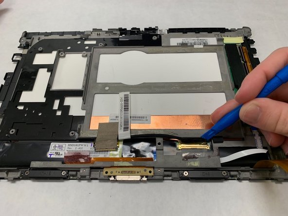
Use fingers, plastic opening tool, or metal spudger to lift the clip securing the display cable and remove by sliding it out.
-
-
Dieser Schritt ist noch nicht übersetzt. Hilf mit, ihn zu übersetzen!
-
Use fingers, plastic opening tool, or metal spudger to lift the glued-in left and right speaker.
-
-
Dieser Schritt ist noch nicht übersetzt. Hilf mit, ihn zu übersetzen!
-
Detach the Wifi and GPS antenna from the screen. This piece is glued down so use a metal spudger to get under the piece and lift up.
-
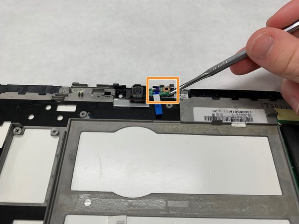
Use a metal spudger to lift up the small electric board next to the camera. This piece is glued down as well as secured by plastic pillars.
-
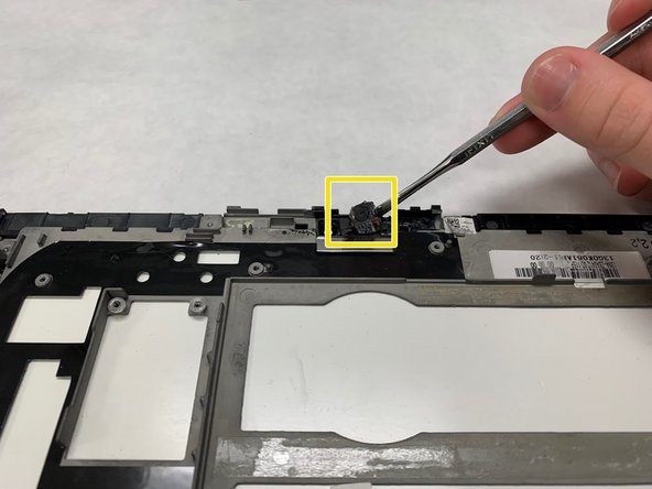
Using a metal spudger, lift the camera out of its spot. The camera is glued down.
-
-
Dieser Schritt ist noch nicht übersetzt. Hilf mit, ihn zu übersetzen!
-
Detach the two ZIF connectors using your fingers, plastic opening tool, or metal spudger.
-
Using a metal spudger lift up the glued down motherboard.
-
-
Dieser Schritt ist noch nicht übersetzt. Hilf mit, ihn zu übersetzen!
-
This is what the final screen should look like after everything is removed.
-


Rückgängig: Ich habe diese Anleitung nicht absolviert.
Ein:e weitere:r Nutzer:in hat diese Anleitung absolviert.
Team

IUPUI, Team S2-G5, Harley Fall 2018 Mitglied von IUPUI, Team S2-G5, Harley Fall 2018
IUPUI-HARLEY-F18S2G5
3 Mitglieder
2 Anleitungen geschrieben
Ein Kommentar
First Class for your Instruction.
With Best Regards
Jürgen Pogoda