Diese Version enthält möglicherweise inkorrekte Änderungen. Wechsle zur letzten geprüften Version.
Was du brauchst
-
Dieser Schritt ist noch nicht übersetzt. Hilf mit, ihn zu übersetzen!
-
Use a Phillips head screw driver to remove the 13 screws in these locations.
-
-
Dieser Schritt ist noch nicht übersetzt. Hilf mit, ihn zu übersetzen!
-
Use a plastic spudger to pry up the bottom cover and remove it.
-
-
Dieser Schritt ist noch nicht übersetzt. Hilf mit, ihn zu übersetzen!
-
Use two fingers to unplug the battery-to-motherboard connection.
-
-
-
Dieser Schritt ist noch nicht übersetzt. Hilf mit, ihn zu übersetzen!
-
Take out battery by lifting it up in the manner pictured.
-
-
Dieser Schritt ist noch nicht übersetzt. Hilf mit, ihn zu übersetzen!
-
Unscrew screw holding SSD card in place.
-
Slide out the SSD card towards you to remove it.
-
-
Dieser Schritt ist noch nicht übersetzt. Hilf mit, ihn zu übersetzen!
-
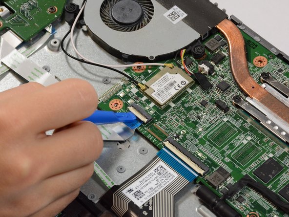
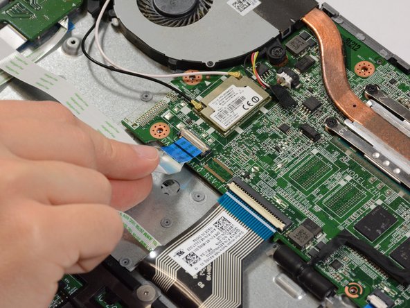
Remove the three ribbon cables connected to the bottom of the motherboard.
-
Use the plastic spudger to lift the white hinges from on top of the ribbon cables.
-
Then gently pull the cables out.
-
-
Dieser Schritt ist noch nicht übersetzt. Hilf mit, ihn zu übersetzen!
-
Remove 4 connectors from the right side of the motherboard.
-
All of these connectors release by simply pulling back.
-
-
Dieser Schritt ist noch nicht übersetzt. Hilf mit, ihn zu übersetzen!
-
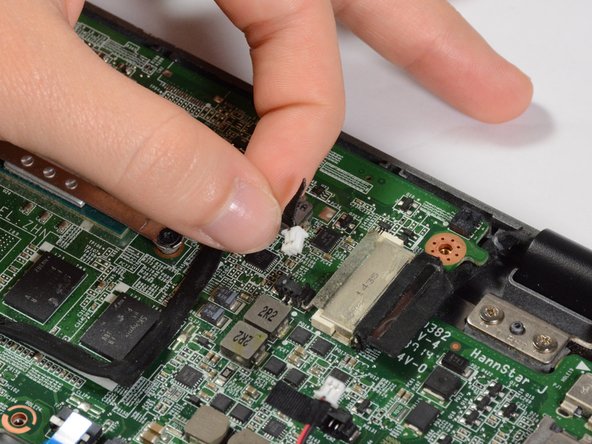
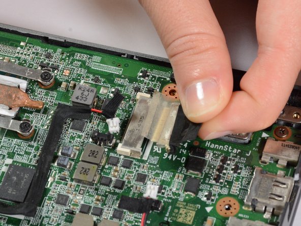
On the left side of the motherboard, remove one more connector and two cables.
-
To remove the cables, lift them up with a plastic spudger.
-
-
Dieser Schritt ist noch nicht übersetzt. Hilf mit, ihn zu übersetzen!
-
Remove the 2 fan screws and the 4 heat sink screws.
-
The screws don't necessarily need to be removed from the component, but rather just loosened enough to remove the component from the motherboard.
-
Now remove the fan/heat sink component.
-
-
Dieser Schritt ist noch nicht übersetzt. Hilf mit, ihn zu übersetzen!
-
Remove the 2 motherboard screws.
-
Now you can remove the motherboard.
-


Rückgängig: Ich habe diese Anleitung nicht absolviert.
Ein:e weitere:r Nutzer:in hat diese Anleitung absolviert.
Team

USF Tampa, Team S9-G3, Remmell Fall 2017 Mitglied von USF Tampa, Team S9-G3, Remmell Fall 2017
USFT-REMMELL-F17S9G3
4 Mitglieder
9 Anleitungen geschrieben