Einleitung
If the display of the Acer Predator 17 G9-791 is completely black or dim. The display might be disabled. To fix this, hold the “Fn” key located near the bottom left of the keyboard and press “F5.” If the display is disabled, this will re-enable the display.
If this does not fix the issue, repeat the above step once more. Then, hold down the Windows key and press “P” twice. The computer may have been set to “Second screen only,” which will set the computer back to “PC screen only.”
If nothing from above fixes the issue, use this guide to replace the display.
Was du brauchst
-
-
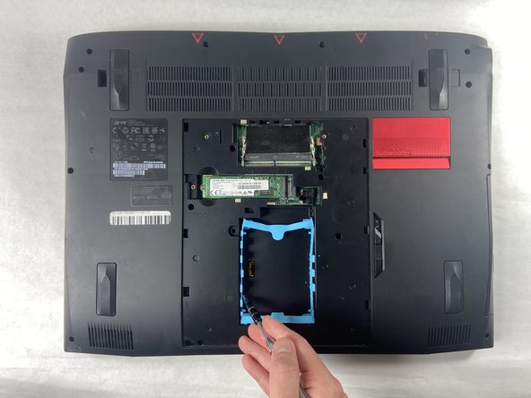
The service panel can be located on the bottom of the device. It is shown here as the panel located in the middle of the device, going from the upper vents to the bottom of the device.
-
-
-
Loosen the two Phillips #0 screws.
-
Pull up slightly on the top of the panel to help fully separate the screws from the rest of the device.
-
-
-
Remove the nine 4.5 mm Phillips #0 screws from the panel.
-
Remove four 14 mm Phillips #0 screws.
-
Remove six 7 mm Phillips #0 screws.
-
-
-
Slide the "unlock" slider up located to the right of the service panel and pull the disc tray out.
-
-
-
Remove the two 4.5 mm Phillips #0 screws located underneath the removed optical drive.
-
-
-
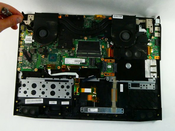
Pry up on the edges of the bottom cover and lift the bottom case off of the device.
-
-
-
-
Remove the five 4.5 mm Phillips #0 screws located on the perimeter of the fans.
-
-
-
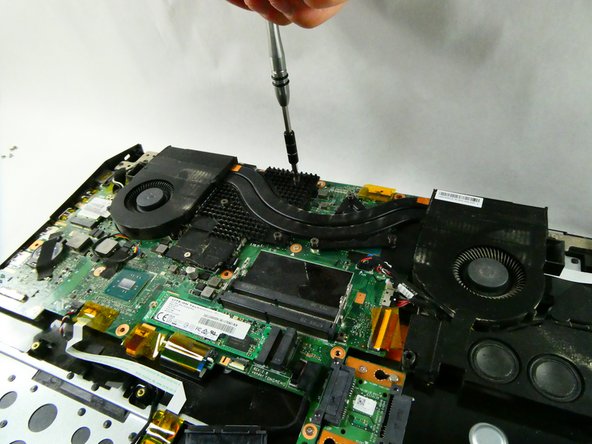
Unscrew the six Phillips #0 screws enough to loosen the assembly from the motherboard.
-
-
-
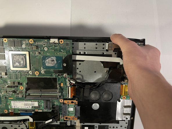
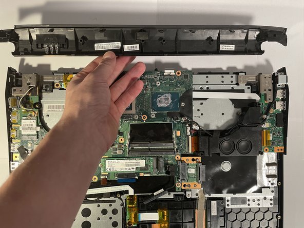
Push down on the back of the device to unclip this panel, removing it by pulling it out the back of the device.
-
-
-
Remove two black 7 mm Phillips #0 screws from the left display bracket.
-
Remove the two silver 5 mm Phillips #0 screws from the left display bracket.
-
-
-
Remove three silver 5 mm Phillips #0 screws from the right display bracket.
-
Remove one black 7 mm Phillips #0 screw from the right display bracket.
-
-
-
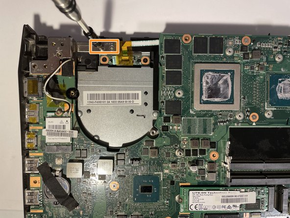
Remove one 4.5 mm Phillips #0 screw from the WLAN card.
-
Pull the WLAN card out.
-
-
-
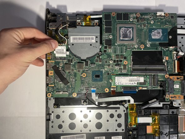
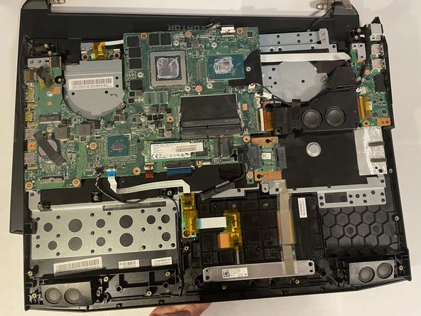
Turn the device around.
-
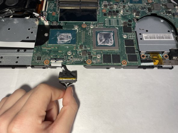
Opening the cover slightly, pull the bottom half of the device towards you.
-
-
-
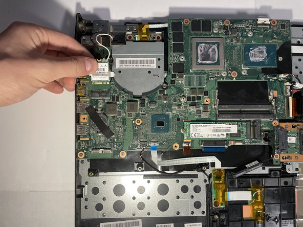
Separate the wire that was unplugged two steps ago from the bottom of the device.
-


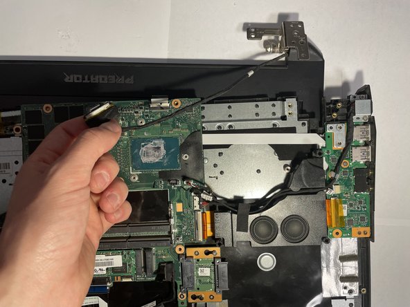
To reassemble your device, follow these instructions in reverse order.
To reassemble your device, follow these instructions in reverse order.

Team

UMass Dartmouth, Team 5-1, Sinclaire Fall 2022 Mitglied von UMass Dartmouth, Team 5-1, Sinclaire Fall 2022
UMASSD-SINCLAIRE-F22S5G1
5 Mitglieder
7 Anleitungen geschrieben