Einleitung
Is the touch screen not working or recognizing input? If so, the touchscreen may be faulty and needs to be replaced. Follow the instructions in this guide to remove and replace the touchscreen in the Acer Spin 3 SP315-51-79NT laptop.
Was du brauchst
-
-
Using the Phillips #1 screwdriver, remove twelve (12) screws from the back panel.
-
-
-
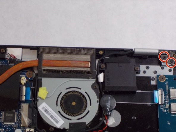
Using the Phillips #1 screwdriver, remove a total of four screws from the hinges (two on each hinge).
-
-
-
-
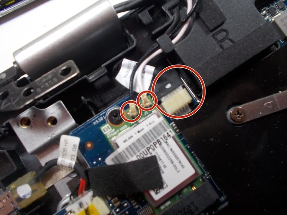
Remove wires connecting to motherboard.
-
You can then simply pull the two halves of the computer away from each other.
-
-
-
Use a spudger to separate the plastic cover from the screen assembly.
-
-
-
Using the Phillips #1 screwdriver, remove the four screws securing the touch screen to the rest of the assembly.
-
-
-
Flip over the touch screen to reveal the circuit board.
-
Disconnect the cable from the circuit board and completely remove the touch screen from the device.
-


To reassemble your device, follow these instructions in reverse order.
To reassemble your device, follow these instructions in reverse order.
Rückgängig: Ich habe diese Anleitung nicht absolviert.
3 weitere Nutzer:innen haben diese Anleitung absolviert.
Team

UMass Dartmouth, Team 2-1, Sinclaire Fall 2021 Mitglied von UMass Dartmouth, Team 2-1, Sinclaire Fall 2021
UMASSD-SINCLAIRE-F21S2G1
3 Mitglieder
6 Anleitungen geschrieben