Diese Version enthält möglicherweise inkorrekte Änderungen. Wechsle zur letzten geprüften Version.
Was du brauchst
-
Dieser Schritt ist noch nicht übersetzt. Hilf mit, ihn zu übersetzen!
-
Use a Phillips #0 Screwdriver to remove the seven Phillips head screws.
-
Separate two halves of clear casing by holding one side and lifting the other.
-
-
Dieser Schritt ist noch nicht übersetzt. Hilf mit, ihn zu übersetzen!
-
Use a Phillips #0 Screwdriver to remove the seven Phillips head screws.
-
Lift motors off of controller.
-
Lift circuit board off of controller.
-
-
Dieser Schritt ist noch nicht übersetzt. Hilf mit, ihn zu übersetzen!
-
Use a Phillips #0 Screwdriver to remove the three screws.
-
Remove triggers by lifting them off the circuit board.
-
Lift the circuit board off of the controller.
-
-
-
Dieser Schritt ist noch nicht übersetzt. Hilf mit, ihn zu übersetzen!
-
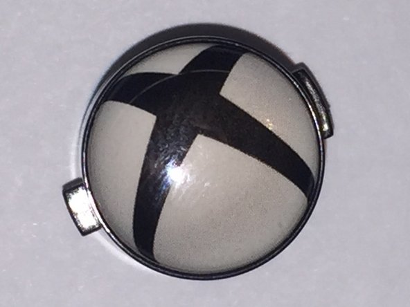
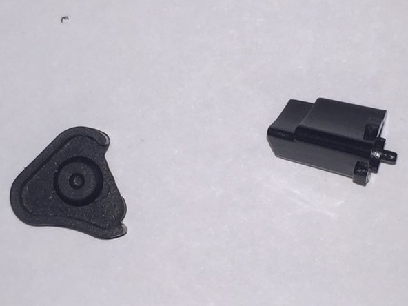
Remove the power and mute button by pulling them out. They will be loose at this point and may fall out by themselves.
-
-
Dieser Schritt ist noch nicht übersetzt. Hilf mit, ihn zu übersetzen!
-
If you've already checked different cords for your controller then you are probably already suspecting something wrong with the USB port on your controller.
-
Using a voltmeter set to check continuity, check each pin inside the female USB connector with it's corresponding gold contact on the board.
-
On the board with the connector facing away from you, the 4 gold contacts are to the right of the connector labeled V, G, D+, and D-. With the connector still faced away from you, the pins for the connector are in order 1-5.
-
Pin 1 = V
-
Pin 2 = D-
-
Pin 3 = D+
-
Pin 4 = G
-
Pin 5 = G
-
-
Dieser Schritt ist noch nicht übersetzt. Hilf mit, ihn zu übersetzen!
-
Pins 4 and 5 are GND1 and Shield1, so they will have continuity with each other. This is normal. We just need to make sure all the gold contacts have continuity to their corresponding pin and aren't crossed with any other pin.
-
If there isn't continuity on one or more of the pins inside the connector, then check the solder on the back of the connector for breaks. If there are breaks use a small heat gun or fine tip soldering iron to melt the break(s) back together.
-
If you now have continuity from the gold contacts to the other end of a cord plugged into the female connector on the board, then reassemble following the teardown guide in reverse order. If this doesn't solve your problem, then proceed to the next step.
-
-
Dieser Schritt ist noch nicht übersetzt. Hilf mit, ihn zu übersetzen!
-
If the inside of the connector is damaged, then you will have to replace it. I've had several devices of mine and my kids that have bad connections due to being bent up or down and it never connects right again.
-
Using a heat gun, heat the connector up enough to melt the solder on all the pins and horns that hold it to the board and gently pull it off the board with needle nose pliers.
-
Inspect the board for damage. If any traces on the board are scratched and exposed, you can dab some super glue on them and let it dry.
-
You can install the new connector with a soldering iron with a fine tip or a small heat gun.
-
Check continuity on your new connector as described earlier in step 5 to make sure it will work with a cord plugged in. Check continuity with a cord plugged in as described in step 6.
-
If problems persist after exhausting all known troubleshooting guides for these controllers, it may be an issue with the board itself.
-
I highly recommend a magnetic tip USB cord for these controllers, because it will simply disconnect if yanked or bent at the controller.
-
-
Dieser Schritt ist noch nicht übersetzt. Hilf mit, ihn zu übersetzen!
-
If you have damaged the traces to the connector like I did, then installing a new connector is not possible or extremely difficult. All is not lost. Simply cut off the connector to an old USB cord, strip the wires, and solder them onto the board as shown in the picture. Cut a slot into the black piece where the connector was and reassemble.
-
Hot glue the opening where your new cord is coming out to prevent movement of the wires and cord. I have tested the controller and it lights up and fully functional again.
-
Rückgängig: Ich habe diese Anleitung nicht absolviert.
2 weitere Nutzer:innen haben diese Anleitung absolviert.


