Diese Version enthält möglicherweise inkorrekte Änderungen. Wechsle zur letzten geprüften Version.
Was du brauchst
-
Dieser Schritt ist noch nicht übersetzt. Hilf mit, ihn zu übersetzen!
-
Use a PH1 screwdriver bit to remove the six M2.5x13 screws (2.4 mm) on the back of the laptop.
-
Use a PH1 screwdriver bit to loosen the one M2x3 screw (1.9 mm).
-
-
Dieser Schritt ist noch nicht übersetzt. Hilf mit, ihn zu übersetzen!
-
Pull the base cover up to remove it.
-
If you are having trouble, insert a plastic opening tool into the divots along the laptop's edges to loosen.
-
-
Dieser Schritt ist noch nicht übersetzt. Hilf mit, ihn zu übersetzen!
-
Disconnect the battery connector cable, located on the right side of the laptop, above the hard disk drive.
-
-
Dieser Schritt ist noch nicht übersetzt. Hilf mit, ihn zu übersetzen!
-
Use a PH1 screwdriver bit to remove the four M2.5x5 screws (2.4 mm) on the hard disk drive.
-
-
Dieser Schritt ist noch nicht übersetzt. Hilf mit, ihn zu übersetzen!
-
Gently lift the HDD cable to disconnect it from the laptop.
-
-
Dieser Schritt ist noch nicht übersetzt. Hilf mit, ihn zu übersetzen!
-
Pull the hard drive up to remove.
-
-
Dieser Schritt ist noch nicht übersetzt. Hilf mit, ihn zu übersetzen!
-
Move the metal sidings outward to release the RAM card.
-
-
Dieser Schritt ist noch nicht übersetzt. Hilf mit, ihn zu übersetzen!
-
Slide the RAM card out towards yourself to remove it.
-
Repeat the same step for the RAM card above.
-
-
-
Dieser Schritt ist noch nicht übersetzt. Hilf mit, ihn zu übersetzen!
-
Peel back plastic cover of wi-fi card.
-
Use a PH1 screwdriver bit and remove the one M2x3 screw (1.9 mm)
-
-
Dieser Schritt ist noch nicht übersetzt. Hilf mit, ihn zu übersetzen!
-
Gently undo the clips attached to the wi-fi card.
-
-
Dieser Schritt ist noch nicht übersetzt. Hilf mit, ihn zu übersetzen!
-
Locate the cables that connect the wi-fi card.
-
Gently pull upwards to remove cables and slide the wi-fi card out from its slot.
-
-
Dieser Schritt ist noch nicht übersetzt. Hilf mit, ihn zu übersetzen!
-
Remove the one M2x3 screw (1.9 mm) using a PH1 screwdriver bit
-
-
Dieser Schritt ist noch nicht übersetzt. Hilf mit, ihn zu übersetzen!
-
Slide the solid state drive towards yourself to prevent damage to the card.
-
-
Dieser Schritt ist noch nicht übersetzt. Hilf mit, ihn zu übersetzen!
-
Remove the two M2.5x7 screws (2.44 mm) located on the rear panel using a PH1 screwdriver bit.
-
-
Dieser Schritt ist noch nicht übersetzt. Hilf mit, ihn zu übersetzen!
-
Insert the plastic opening tool under the fan shroud to slowly lift it up.
-
Repeat process on the middle and opposite side.
-
-
Dieser Schritt ist noch nicht übersetzt. Hilf mit, ihn zu übersetzen!
-
Firmly lift the plastic opening tool and pull the fan shroud towards you.
-
-
Dieser Schritt ist noch nicht übersetzt. Hilf mit, ihn zu übersetzen!
-
Unscrew the two M2x3 screws (1.9 mm) at the top right and top left of the laptop that hold the tron lights in place.
-
-
Dieser Schritt ist noch nicht übersetzt. Hilf mit, ihn zu übersetzen!
-
Follow the wiring to unplug the tron lights.
-
-
Dieser Schritt ist noch nicht übersetzt. Hilf mit, ihn zu übersetzen!
-
Remove the fourteen M2.5XL8' screws (2.4 mm) located in the plastic cover using the PH1 screwdriver.
-
-
Dieser Schritt ist noch nicht übersetzt. Hilf mit, ihn zu übersetzen!
-
Use the plastic opening tool to gently lift the sides of the cover.
-
-
Dieser Schritt ist noch nicht übersetzt. Hilf mit, ihn zu übersetzen!
-
Slowly lift up the plastic cover.
-
-
Dieser Schritt ist noch nicht übersetzt. Hilf mit, ihn zu übersetzen!
-
Unscrew the four M2.5 screws (2.4 mm) with a PH1 screwdriver bit.
-
-
Dieser Schritt ist noch nicht übersetzt. Hilf mit, ihn zu übersetzen!
-
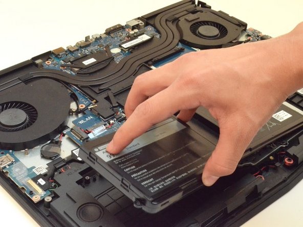
Lift the battery up to remove it.
-


Rückgängig: Ich habe diese Anleitung nicht absolviert.
26 weitere Nutzer:innen haben diese Anleitung absolviert.
Team

CSU Fullerton, Team S2-G4, Bruce Fall 2017 Mitglied von CSU Fullerton, Team S2-G4, Bruce Fall 2017
CSUF-BRUCE-F17S2G4
4 Mitglieder
9 Anleitungen geschrieben
7 Kommentare
Very good guide, just one error, step 11 comes first then step 10. You can't lift the card before remove the screw.
Great guide, no issues at all!
I would not recommend disconnecting the wifi card. the connectors are tiny. if you screw up, best case you need a new wifi card, worst case you are going to need to replace the antenna, and that isn’t fun.
After the battery replacement? do we need to do anything else for calibration so that the Alienware knows that it is a fresh battery and battery cycle ... as i have heard that you need to repeat 3X the process of discharging and charging for calibration. or can we just plug and play? I am getting a new battery for mine soon. Thanks =)