Diese Version enthält möglicherweise inkorrekte Änderungen. Wechsle zur letzten geprüften Version.
Was du brauchst
-
Dieser Schritt ist noch nicht übersetzt. Hilf mit, ihn zu übersetzen!
-
Use the spudger to remove the eight black pins from the front and back of the wire screens.
-
-
Dieser Schritt ist noch nicht übersetzt. Hilf mit, ihn zu übersetzen!
-
Detach the eight secondary pins from the front and back of the wire mesh plates with a spudger.
-
-
Dieser Schritt ist noch nicht übersetzt. Hilf mit, ihn zu übersetzen!
-
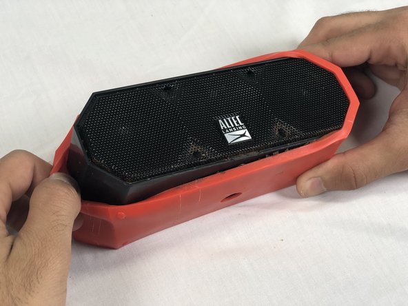
Remove both black and orange layers from the speaker body.
-
-
Dieser Schritt ist noch nicht übersetzt. Hilf mit, ihn zu übersetzen!
-
Remove the single 7.8mm Phillips #2 screw from the mounting plate located under the device.
-
Slide the mounting plate out to remove it.
-
-
-
Dieser Schritt ist noch nicht übersetzt. Hilf mit, ihn zu übersetzen!
-
Pry off the wire mesh on both sides using a metal spudger.
-
-
Dieser Schritt ist noch nicht übersetzt. Hilf mit, ihn zu übersetzen!
-
Using tweezers, remove the four rubber stoppers in each corner of the rear panel.
-
-
Dieser Schritt ist noch nicht übersetzt. Hilf mit, ihn zu übersetzen!
-
Remove the four 13.7mm Phillips #1 screws located underneath the rubber stoppers.
-
-
Dieser Schritt ist noch nicht übersetzt. Hilf mit, ihn zu übersetzen!
-
Pull the case apart to access the interior components.
-
-
Dieser Schritt ist noch nicht übersetzt. Hilf mit, ihn zu übersetzen!
-
To remove the back panel, gently pull out its wire harness.
-
-
Dieser Schritt ist noch nicht übersetzt. Hilf mit, ihn zu übersetzen!
-
Remove the three 9.3 mm Phillips #1 screws on the speaker cover.
-
-
Dieser Schritt ist noch nicht übersetzt. Hilf mit, ihn zu übersetzen!
-
To remove the speaker, gently pull out the its wire harness.
-
-
Dieser Schritt ist noch nicht übersetzt. Hilf mit, ihn zu übersetzen!
-
Remove the rubber ring from the rim of the speaker.
-


Rückgängig: Ich habe diese Anleitung nicht absolviert.
Ein:e weitere:r Nutzer:in hat diese Anleitung absolviert.
Team

USF Tampa, Team S3-G2, Nance Spring 2018 Mitglied von USF Tampa, Team S3-G2, Nance Spring 2018
USFT-NANCE-S18S3G2
4 Mitglieder
4 Anleitungen geschrieben
2 Kommentare
What speaker should we be getting to replace the faulty speaker, including the wires needed to plug into the slots on the board?
Where can I get this speaker parts?