Diese Version enthält möglicherweise inkorrekte Änderungen. Wechsle zur letzten geprüften Version.
Was du brauchst
-
Dieser Schritt ist noch nicht übersetzt. Hilf mit, ihn zu übersetzen!
-
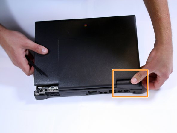
Position the Powerbook towards you with the monitor closed.
-
Press the battery removal latch located on the right side of the front panel.
-
Gently slide the battery out.
-
-
Dieser Schritt ist noch nicht übersetzt. Hilf mit, ihn zu übersetzen!
-
Turn the laptop over and remove the three T8 torx screws from the bottom panel.
-
-
Dieser Schritt ist noch nicht übersetzt. Hilf mit, ihn zu übersetzen!
-
Turn the laptop back over and open the monitor.
-
With the monitor facing towards you, gently pull up on the keyboard panel from the bottom.
-
-
Dieser Schritt ist noch nicht übersetzt. Hilf mit, ihn zu übersetzen!
-
Begin by locating the side panel covers.
-
Remove the side panels by pulling up and towards the rear of the laptop.
-
Remove the two Torx #8 screws using a TR8 Torx security screwdriver.
-
-
Dieser Schritt ist noch nicht übersetzt. Hilf mit, ihn zu übersetzen!
-
Turn the laptop upside down.
-
Remove the three Torx #8 screws.
-
Turn the laptop right side up, then lift up the keyboard.
-
-
Dieser Schritt ist noch nicht übersetzt. Hilf mit, ihn zu übersetzen!
-
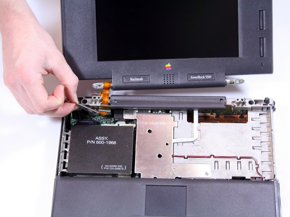
Disconnect the ribbon cable from the logic board.
-
-
-
Dieser Schritt ist noch nicht übersetzt. Hilf mit, ihn zu übersetzen!
-
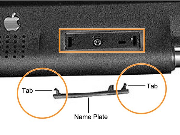
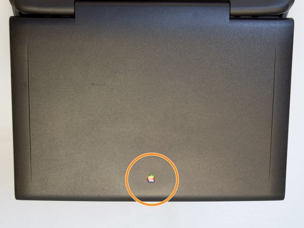
Use a pin to pry up the Powerbook 5300 and Macintosh logos to reveal two screws.
-
Using a spudger, remove the two product nameplates to expose the underlying screws.
-
Remove two Torx #8 screws.
-
-
Dieser Schritt ist noch nicht übersetzt. Hilf mit, ihn zu übersetzen!
-
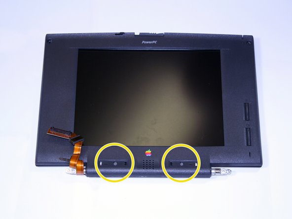
Remove the four screws holding the bezel to the back display housing.
-
Turn the display face down with the Apple logo facing towards you.
-
Starting at the bottom of the display housing, carefully pry the plastics apart at the six inner latch locations using a spudger.
-
-
Dieser Schritt ist noch nicht übersetzt. Hilf mit, ihn zu übersetzen!
-
Use a prying tool to open the two halves of the display assembly.
-
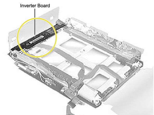
Lift the top half away from the bottom half to expose the inverter board.
-
Look for the barcode on the left to be sure you have reached the inverter board.
-
-
Dieser Schritt ist noch nicht übersetzt. Hilf mit, ihn zu übersetzen!
-
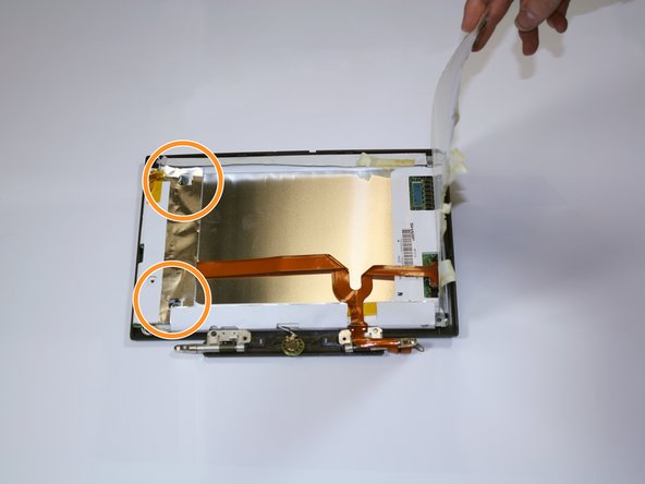
Unscrew the three Torx #8 screws above the white paper backing holding the display to the bezel.
-
Unscrew the three Torx #8 screws below the white paper backing.
-
Remove the tape and peel back the paper backing to access the screws below. Lay back the display EMI insulator and gently lift the inverter board.
-
-
Dieser Schritt ist noch nicht übersetzt. Hilf mit, ihn zu übersetzen!
-
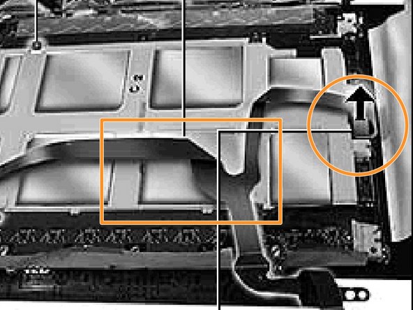
Carefully, rotate the inverter board so that it is lying face up near the middle of the display.
-
Disconnect the four cables from the inverter board.
-
-
Dieser Schritt ist noch nicht übersetzt. Hilf mit, ihn zu übersetzen!
-
Remove the two remaining screws holding the display to the display bezel.
-
Disconnect the display cable from the display by gently pulling straight up on the reinforced backing of the cable.
-
-
Dieser Schritt ist noch nicht übersetzt. Hilf mit, ihn zu übersetzen!
-
Lift the entire paper and monitor assembly out of its casing. Remove the display from the bezel.
-
Remove the display EMI insulator.
-
Pull up the actual monitor out of its paper shell.
-
-
Dieser Schritt ist noch nicht übersetzt. Hilf mit, ihn zu übersetzen!
-
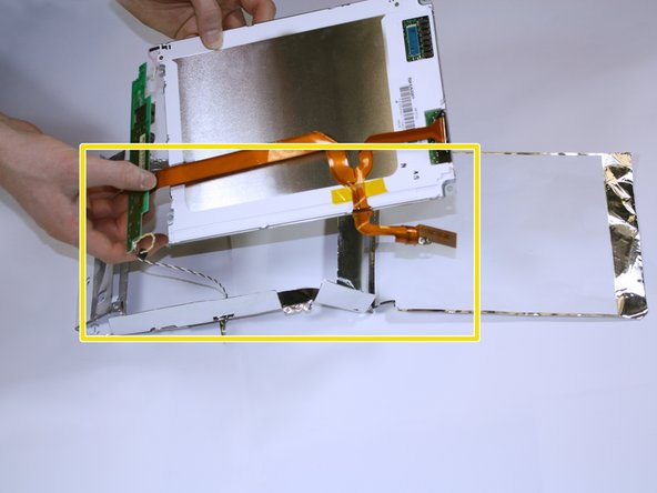
Remove the entire display EMI insulator from the casing.
-
-
Dieser Schritt ist noch nicht übersetzt. Hilf mit, ihn zu übersetzen!
-
Replace the new display EMI Insulator.
-
-
Dieser Schritt ist noch nicht übersetzt. Hilf mit, ihn zu übersetzen!
-
Replace the screen cover after following steps 7-12 in reverse order.
-
Turn over the display and replace the four bezel screws.
-
Follow steps 1-5 in reverse order to attach the monitor and keyboard back to the unit. Then turn on the laptop to ensure the display is properly working.
-


Rückgängig: Ich habe diese Anleitung nicht absolviert.
2 weitere Nutzer:innen haben diese Anleitung absolviert.
Team

Cal Poly, Team 25-30, Garner Spring 2011 Mitglied von Cal Poly, Team 25-30, Garner Spring 2011
CPSU-GARNER-S11S25G30
4 Mitglieder
6 Anleitungen geschrieben