Zum Hauptinhalt wechseln

BlackBerry 7510 Logic Board Replacement

Was du brauchst

  1. BlackBerry 7510 Logic Board Replacement, Back Face of Phone: Schritt 1, Bild 1 von 1
    • Remove the battery cover and battery before continuing.

    • Remove the six T6 Torx screws on the back of the phone.

    • Make sure to keep the screws somewhere that they will not get lost.

  2. BlackBerry 7510 Logic Board Replacement: Schritt 2, Bild 1 von 1
    • Using your finger nail or a spudger, carefully pry up the back cover.

    • Begin in one spot and slowly circle around the device as you pry up all of the back cover.

  3. BlackBerry 7510 Logic Board Replacement: Schritt 3, Bild 1 von 1
    • Lift off the back cover.

  4. BlackBerry 7510 Logic Board Replacement: Schritt 4, Bild 1 von 1
    • Remove the two T6 screws.

  5. BlackBerry 7510 Logic Board Replacement: Schritt 5, Bild 1 von 2 BlackBerry 7510 Logic Board Replacement: Schritt 5, Bild 2 von 2
    • Remove the daughterboard.

    • Remove the exposed vibration motor.

  6. BlackBerry 7510 Logic Board Replacement, Logic Board: Schritt 6, Bild 1 von 1
    • Using the T6 Torx screwdriver, remove the top screw.

  7. BlackBerry 7510 Logic Board Replacement: Schritt 7, Bild 1 von 1
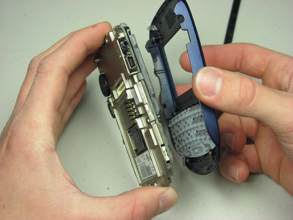
    • Using your spudger, carefully pry off back plate.

    • Use the same technique as with the plastic back cover. Circle around the back plate until all of it is pried up.

  8. BlackBerry 7510 Logic Board Replacement: Schritt 8, Bild 1 von 1
    • Remove the front cover and keypad.

  9. BlackBerry 7510 Logic Board Replacement: Schritt 9, Bild 1 von 1
    • Remove one T6 Torx screw in the front bottom right of the board.

  10. BlackBerry 7510 Logic Board Replacement: Schritt 10, Bild 1 von 2 BlackBerry 7510 Logic Board Replacement: Schritt 10, Bild 2 von 2
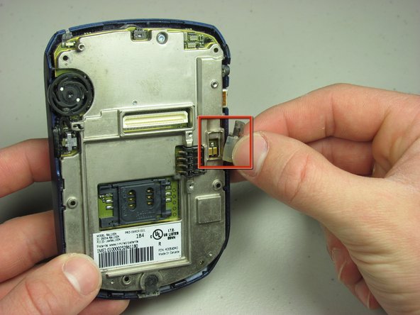
    • Carefully pry the screen from the board with your spudger.

    • After prying it up, remove the screen from the board.

  11. BlackBerry 7510 Logic Board Replacement: Schritt 11, Bild 1 von 2 BlackBerry 7510 Logic Board Replacement: Schritt 11, Bild 2 von 2
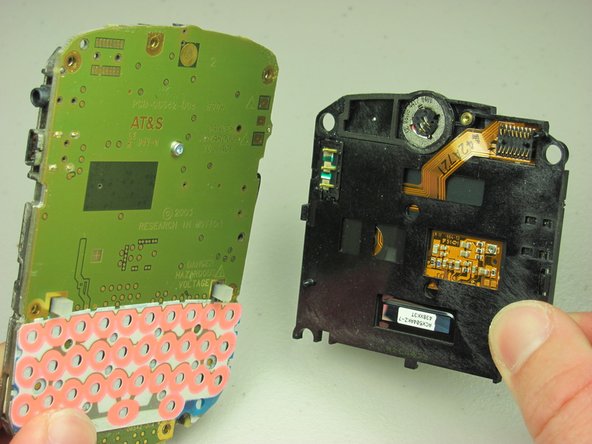
    • Unscrew center T6 Torx screw in the center of the logic board.

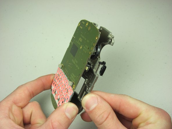
    • Remove the logic board from the phone.

    • Replace with new logic board.

Abschluss

To reassemble your device, follow these instructions in reverse order.

Neil Johnson

Mitglied seit: 01/24/10

12 Reputation

6 Anleitungen geschrieben

Team

Cal Poly, Team 14-44, Regan Winter 2010 Mitglied von Cal Poly, Team 14-44, Regan Winter 2010

CPSU-REGAN-W10S14G44

4 Mitglieder

8 Anleitungen geschrieben

0 Kommentare

Kommentar hinzufügen

Seitenaufrufe:

Letzte 24 Stunden: 0

Letzte 7 Tage: 0

Letzte 30 Tage: 1

Insgesamt: 1,846