Diese Version enthält möglicherweise inkorrekte Änderungen. Wechsle zur letzten geprüften Version.
Was du brauchst
-
Dieser Schritt ist noch nicht übersetzt. Hilf mit, ihn zu übersetzen!
-
Locate the two switches toward the bottom corners of the device's back cover.
-
Use your thumbs or fingers to push the two switches forward at the same time and detach the back cover from the device.
-
Check to make sure the back cover has fully detached from the device. You should be left with two separate pieces: the back cover, and the device with exposed internal hardware.
-
-
Dieser Schritt ist noch nicht übersetzt. Hilf mit, ihn zu übersetzen!
-
Identify that the battery is visible once the back cover has been removed, and locate the battery in the rectangular-shaped top half of the device.
-
Pry apart the battery and back of the device using the flat end of your spudger tool or using your finger if you do not have a spudger.
-
-
Dieser Schritt ist noch nicht übersetzt. Hilf mit, ihn zu übersetzen!
-
Locate the SIM card once the battery has been removed. The SIM card is typically located in the center of the phone, and it is secured by a metal tray.
-
-
Dieser Schritt ist noch nicht übersetzt. Hilf mit, ihn zu übersetzen!
-
Remove the SIM card carefully by sliding it upwards out of the metal tray. No tools are needed for this step.
-
-
Dieser Schritt ist noch nicht übersetzt. Hilf mit, ihn zu übersetzen!
-
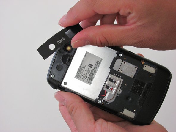
Place the opening tool underneath the camera lens' protective plastic cover and pry them apart with gentle force.
-
Make sure the plastic cover has been fully removed by carefully lifting it away from the device with your fingers.
-
-
Dieser Schritt ist noch nicht übersetzt. Hilf mit, ihn zu übersetzen!
-
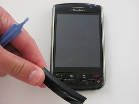
Flip the device so that the touchscreen and Blackberry logo is facing you.
-
Place the opening tool underneath the front plastic cover located below the buttons with red and green phone symbols.
-
Lift and remove the plastic cover once the opening tool is in place. Make sure the plastic cover can be fully detached from the rest of the device.
-
-
Dieser Schritt ist noch nicht übersetzt. Hilf mit, ihn zu übersetzen!
-
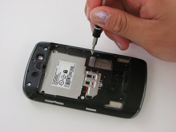
Remove the two bronze Torx T6 3 mm screws below the red and green phone symbols.
-
-
-
Dieser Schritt ist noch nicht übersetzt. Hilf mit, ihn zu übersetzen!
-
Remove the four silver Torx T6 3 mm screws on the back of the device.
-
-
Dieser Schritt ist noch nicht übersetzt. Hilf mit, ihn zu übersetzen!
-
Pry the opening tool into the slit between the two plastic sides of the device to separate the back panel from the front panel.
-
Slide the opening tool across the slit until you are left with two, separated front and back panels.
-
-
Dieser Schritt ist noch nicht übersetzt. Hilf mit, ihn zu übersetzen!
-
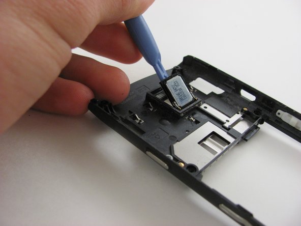
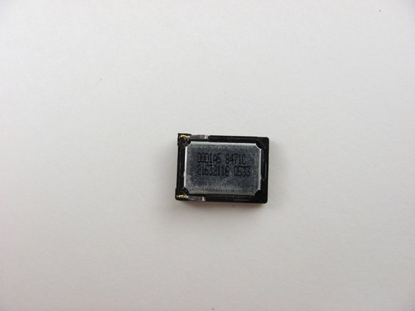
Locate the silver speaker marked with numbers and letters on the back panel of the device.
-
-
Dieser Schritt ist noch nicht übersetzt. Hilf mit, ihn zu übersetzen!
-
Place the opening tool underneath the silver speaker component.
-
Use the opening tool to lift the speaker off of the panel with light force.
-
Set the speaker aside once it has been fully removed.
-
-
Dieser Schritt ist noch nicht übersetzt. Hilf mit, ihn zu übersetzen!
-
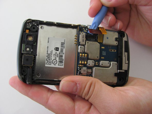
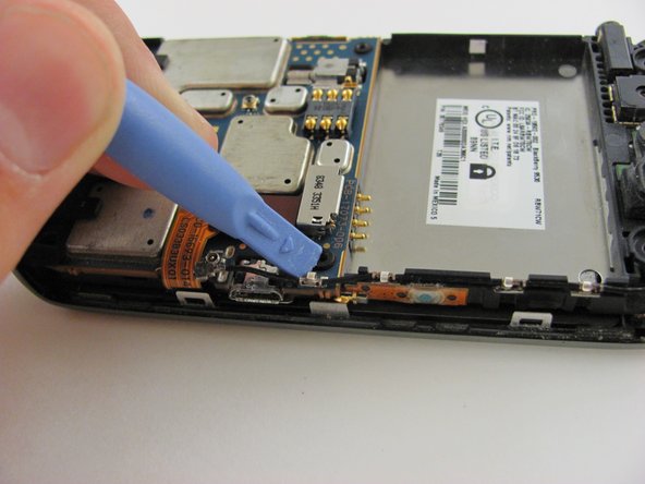
Locate the red tabbed pin strip connected to the motherboard. The red tabbed pin strip is located on the right-hand side of the back of the phone.
-
Disconnect the red tabbed pin strip from the motherboard by inserting the opening tool under the side of the tab and gently pulling upwards toward you.
-
-
Dieser Schritt ist noch nicht übersetzt. Hilf mit, ihn zu übersetzen!
-
Locate the yellow tabbed pin strip which is directly next to the original location of the red tabbed pin strip.
-
Disconnect the yellow tabbed pin strip from the motherboard using the same technique used to disconnect the red tabbed pin strip in the previous step.
-
-
Dieser Schritt ist noch nicht übersetzt. Hilf mit, ihn zu übersetzen!
-
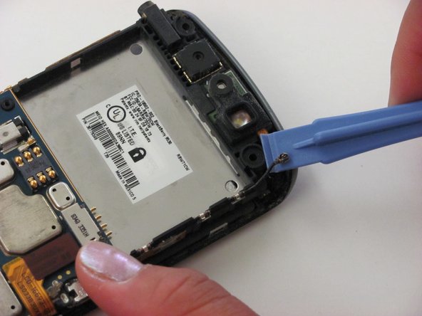
Disconnect the antenna cable located at the top right corner of the black panel using the opening tool.
-
Insert the opening tool underneath the side of the antenna connection, and gently pull upwards to disconnect the cable.
-
-
Dieser Schritt ist noch nicht übersetzt. Hilf mit, ihn zu übersetzen!
-
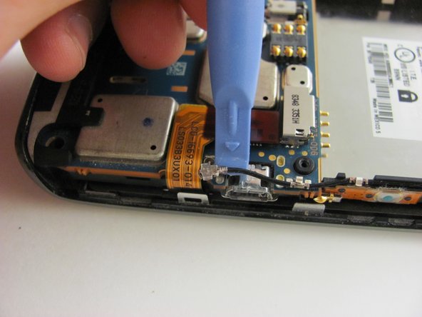
Locate the second antenna connection toward the middle right area of the back panel. It is found in the corner where the red and yellow tabbed pin strips met.
-
Remove the antenna connection using the same method done in the previous, top antenna removal step.
-
Loosen the bottom metal cable grip (which pins down the cable) to separate the antenna from the motherboard entirely.
-
-
Dieser Schritt ist noch nicht übersetzt. Hilf mit, ihn zu übersetzen!
-
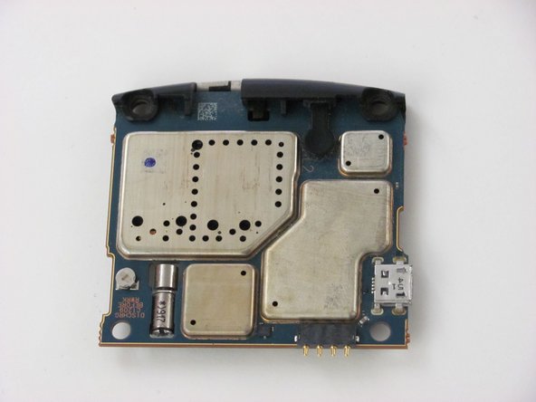
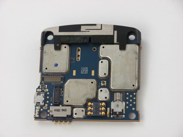
Remove the entire motherboard now that all the components holding it down have been removed or disconnected.
-
Grip the top right edge of the motherboard with your fingers and remove it by pulling it out gently.
-
-
Dieser Schritt ist noch nicht übersetzt. Hilf mit, ihn zu übersetzen!
-
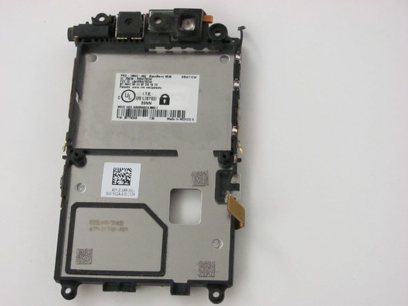
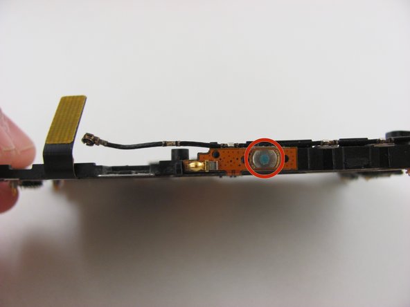
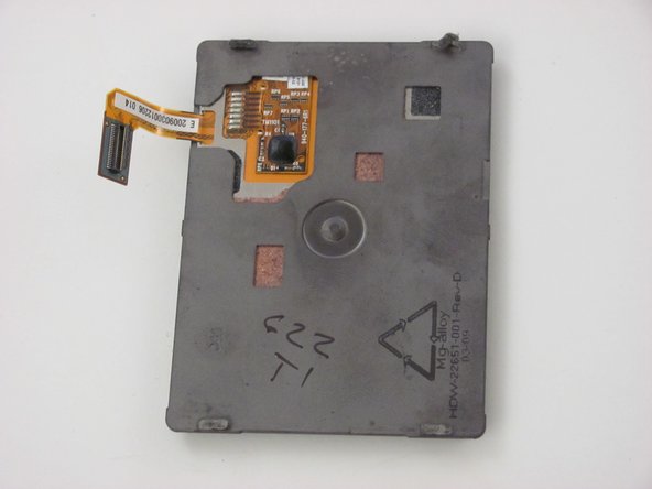
Hold the middle panel and lift it away from the frame to separate the middle button panel from the screen and front frame.
-
Set the middle button panel aside after it has been fully separated from the screen.
-
-
Dieser Schritt ist noch nicht übersetzt. Hilf mit, ihn zu übersetzen!
-
On the underside of the middle panel is the screen button and accessory parts.
-
Replace the circled screen button (if needed) by replacing the entire middle panel.
-
-
Dieser Schritt ist noch nicht übersetzt. Hilf mit, ihn zu übersetzen!
-
Replace the volume control and convenience key buttons by replacing the entire middle panel.
-
-
Dieser Schritt ist noch nicht übersetzt. Hilf mit, ihn zu übersetzen!
-
Notice that the LCD/touchscreen is placed directly beneath the side button panel.
-
Prepare to remove the The LCD/touchscreen which rests directly on top of the front panel of the phone.
-
Remove the LCD/touchscreen by pulling it off of the front panel once you have located it. No tools are necessary.
-


Rückgängig: Ich habe diese Anleitung nicht absolviert.
3 weitere Nutzer:innen haben diese Anleitung absolviert.
Team

Cal Poly, Team 9-16, Regan Spring 2014 Mitglied von Cal Poly, Team 9-16, Regan Spring 2014
CPSU-REGAN-S14S9G16
4 Mitglieder
10 Anleitungen geschrieben