Diese Version enthält möglicherweise inkorrekte Änderungen. Wechsle zur letzten geprüften Version.
Was du brauchst
-
Dieser Schritt ist noch nicht übersetzt. Hilf mit, ihn zu übersetzen!
-
On the back of the device, remove the four 3/8" Torx head screws using the T-6 Torx bit.
-
-
Dieser Schritt ist noch nicht übersetzt. Hilf mit, ihn zu übersetzen!
-
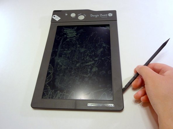
Remove the stylus if it is in the housing at the top of the device.
-
Turn the device so you are looking at it from the top down.
-
Using your thumbs on each wall of the stylus housing, open the frame of the device by gently pulling the two sides apart.
-
-
Dieser Schritt ist noch nicht übersetzt. Hilf mit, ihn zu übersetzen!
-
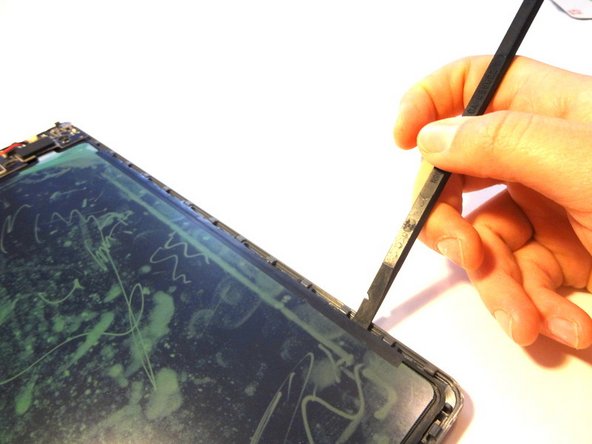
Insert a spudger into the seam between the front and back plates of the frame. Unsnap the snaps around the entire frame of the device.
-
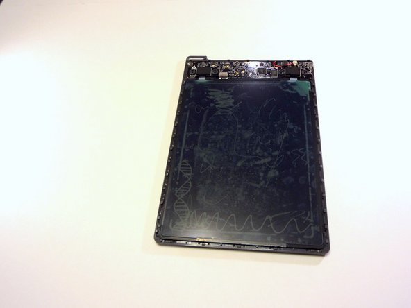
Remove the front face plate by pulling it straight up.
-
-
Dieser Schritt ist noch nicht übersetzt. Hilf mit, ihn zu übersetzen!
-
Use a spudger (or gently bend the back plate of the device) to unsnap the snaps holding the screen in place.
-
-
Dieser Schritt ist noch nicht übersetzt. Hilf mit, ihn zu übersetzen!
-
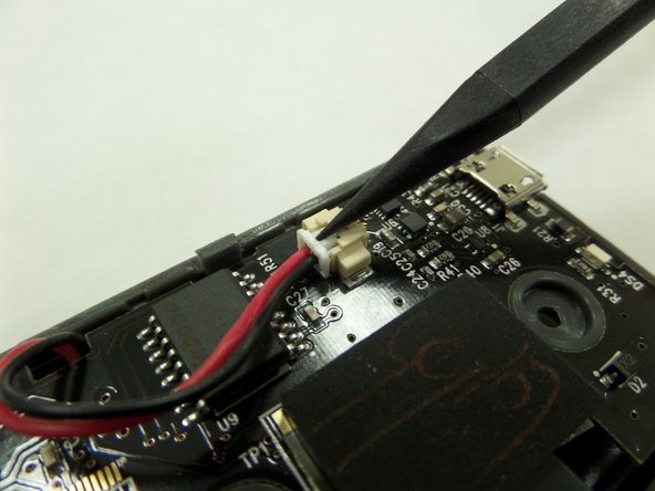
With a spudger, press against the lip of the connector closest to the wires to remove the battery connector from the motherboard.
-
-
-
Dieser Schritt ist noch nicht übersetzt. Hilf mit, ihn zu übersetzen!
-
Gently lift the motherboard with a spudger or small object by inserting it in the seam between the back frame and the motherboard.
-
Remove the battery hidden behind the motherboard.
-
-
Dieser Schritt ist noch nicht übersetzt. Hilf mit, ihn zu übersetzen!
-
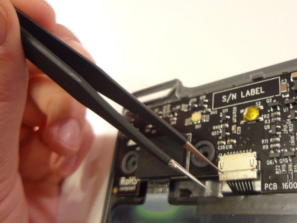
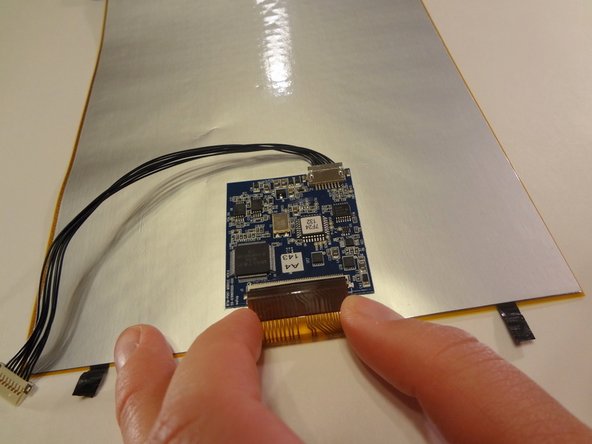
Use a pair of tweezers or a small, pointed object to gently pull the connector out on both the left and right sides.
-
-
Dieser Schritt ist noch nicht übersetzt. Hilf mit, ihn zu übersetzen!
-
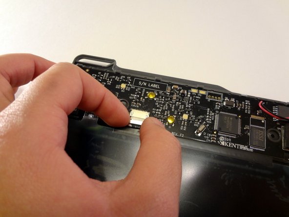
Once you see an even white line of the plastic pin casing appear (about 1 mm), use your index finger and thumb to pull the connector straight out from the motherboard.
-
-
Dieser Schritt ist noch nicht übersetzt. Hilf mit, ihn zu übersetzen!
-
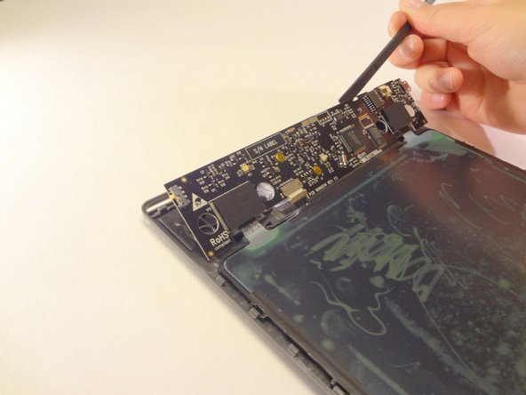
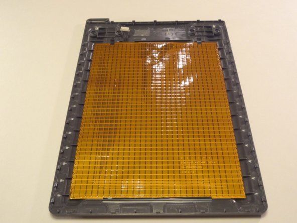
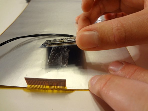
Using a spudger or prying tool, lift the connected screen and motherboard straight up to expose the gold-colored antenna taped to the back plate.
-
-
Dieser Schritt ist noch nicht übersetzt. Hilf mit, ihn zu übersetzen!
-
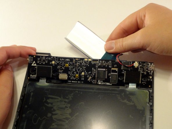
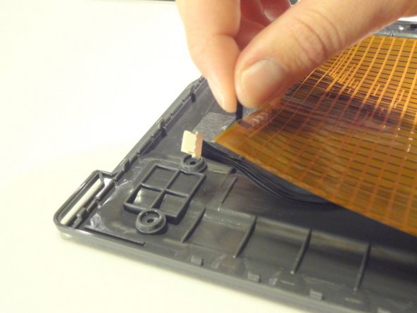
Using a spudger or your fingernail, remove the black electrical tape securing the antenna to the black plate.
-
-
Dieser Schritt ist noch nicht übersetzt. Hilf mit, ihn zu übersetzen!
-
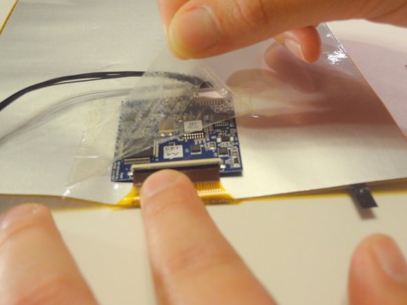
On the back side of the antenna, use a spudger or your fingernail to remove the transparent tape holding the transformer to the antenna.
-
-
Dieser Schritt ist noch nicht übersetzt. Hilf mit, ihn zu übersetzen!
-
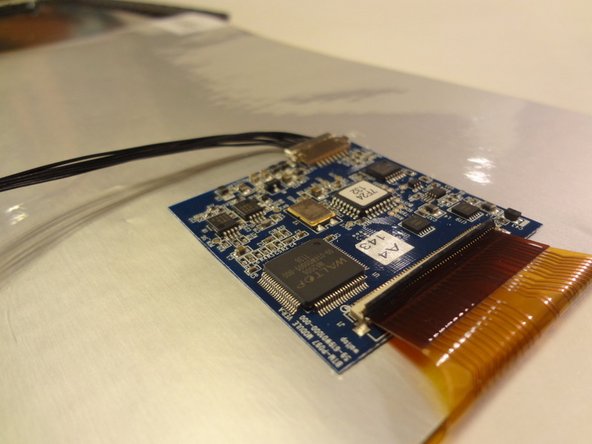
Using a spudger or the nail of your thumb, lift the black cover securing the antenna to the transformer up and away from yourself.
-
Using your index finger and thumb, disconnect the antenna from the transformer.
-
-
Dieser Schritt ist noch nicht übersetzt. Hilf mit, ihn zu übersetzen!
-
Gently pull apart the transformer from the back of the anenna.
-


Rückgängig: Ich habe diese Anleitung nicht absolviert.
Ein:e weitere:r Nutzer:in hat diese Anleitung absolviert.
Team

CSU Fullerton, Team 2-6, Bruce Fall 2014 Mitglied von CSU Fullerton, Team 2-6, Bruce Fall 2014
CSUF-BRUCE-F14S2G6
4 Mitglieder
6 Anleitungen geschrieben