Einleitung
Für diese Anleitung haben wir einen CR-10S Pro zerlegt, damit wir besser zeigen können, wie man ein BL Touch-Kit installiert. Wenn du dein Gerät zusammengebaut lässt, sind die Vorgangsweisen die gleichen, aber du musst die Baufläche schützen, wenn du sie als Workstation verwenden wollen. Die Schwerkraft kann nicht deaktiviert werden, vergiss das nicht..
Lese diese Schritte durch, bevor du beginnst:
- Gehe den gesamten Vorgang durch, bevor du eine Komponente aus deiner Maschine entfernst. Stelle sicher, dass du mit den Aufgaben vertraut bist und diese ausführen kannst
- Vergewissere dich, dass du eine USB-Verbindung zu deinem Gerät hast. Du kannst zuerst versuchen, die Firmware des Mainboards zu flashen. Wenn es dann ein Problem gibt, hast du immer noch ein funktionierendes Gerät und kannst das USB-Problem vor dem Upgrade beheben.
- Stelle sicher, dass du die nötige Zeit und die Werkzeuge für das Upgrade hast. Es macht keinen Spaß, wenn du auf halbem Weg zu einer Aufgabe bist und diese abbrechen musst, weil dir etwas fehlt.
Was du brauchst
-
-
Löse die Innensechskantschrauben, mit denen die Riemenleitrolle der X-Achse befestigt ist, mit einem M3-Inbus.
-
Schiebe die Riemenspannrolle der X-Achse nach links, um die Riemenspannung zu lösen.
-
Entferne die Riemenenden vom Schlitten der X-Achse.
-
Löse die Befestigungselemente, die das untere Rad in Position halten, mit dem doppelseitigen Schraubenschlüssel und dem M3-Sechskant, bis die. Entferne die Mutter nicht vollständig.
-
Entferne die Knopfschrauben mit einem M2-Inbus.
-
-
-
Entferne die X-Achsen-Baugruppe von der Maschine.
-
Schneide den Kabelbinder durch
-
Entferne von der Rückseite her die Knopfschrauben mit einem M2-Inbus. Dadurch werden die ursprüngliche Sonde und die Halterung gelöst.
-
Befestige die BL Touch-Halterung mit denselben Schrauben wie abgebildet.
-
Die Sonde wird wie gezeigt installiert, aber lasse sie vorerst lose. Der Kabelbaum lässt sich leichter anschließen, wenn die Sonde entfernt ist.
-
Die mitgelieferten M3x 6-Knopfschrauben dienen zur Befestigung der Sonde.
-
-
-
Schneide 2 Kabelbinder ab.
-
Entferne die 3 Flachkopfschrauben mit M2-Inbus, um die Abdeckung der Tochterkarte zu entfernen.
-
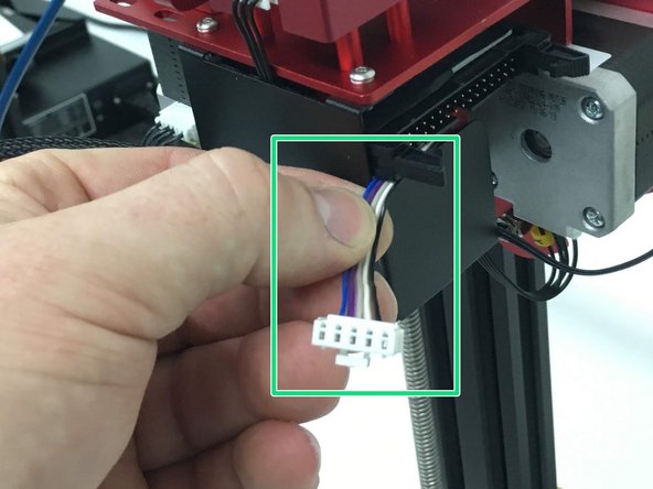
Ziehe den Stecker der Originalsonde ab. Möglicherweise ist er verklebt, ziehe also am Stecker, nicht an den Drähten.
You should use a picture of the board from the top down. The current picture is very confusing of the daughter board.
Where is the jumper install instructions? Vital for the CR10S Pro!
So is it true that with the CR10S Pro, that no jumper is needed with your new firmware, if the Z+ connector is used in lieu of the Z- connector? Just checking, because when the former owner of this printer upgraded it, he uses a jumper and the Z- connector. So I’m changing to the Z+ connector and
Following this guide 03/2023. You can use the Z- and the jumper using the right firmware, yet as the Z+ is not used, it's easier to just use that port (no need for jumper).
What's confusing is that in TM's manual, they refer to firmware for the CR-10S Pro and the CR-10S Pro V2. But as they're essentially the same device with a few minor tweaks (bltouch and glass print bed for V2 vs. capacitive sensor and aluminum bed for V1), the firmware is the same for both.
-
-
-
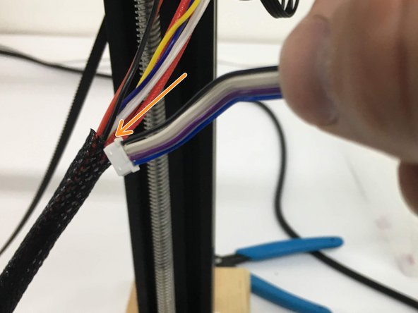
Ziehe die ursprüngliche Sonde auf der gegenüberliegenden Seite heraus, um sie aus dem Kabelbaum zu entfernen.
-
Führe den neuen Sondenkabelbaum von der Tochterplattenseite her ein, wobei der kleine Stecker (Sondenseite) zuerst eingeführt wird. Wenn der Kabelbaum noch gedehnt ist, solltest du ihn vollständig durchstecken können.
-
Lasse ca. 1-1,5 Zoll des Endes des Sondenkabelbaums neben dem Flachbandkabelanschluss frei und bringe die Abdeckung der Tochterkarte wieder an.
where is the step on how to connect up that 5 pin sensor connector to the daughter board? i am at a loss there as the old connecter is only 3 pins
You don't connect the 5 pin sensor line to the daughter board, you connect it to the ribbon cable -- there's a 5-pin plug at the daughter board end.
If you bought the TinyMachines kit, there should be a specific 5-pin connector on the BLtouch, and a 5-pin connector on the included ribbon cable.
If you are using a generic BLtouch kit, you need to route the wires to the inside of the printer base (I went through the same opening as the ribbon cable)
-
-
-
Ziehe die Flachkopfschrauben mit M2-Inbus an. Beginne mit den oberen 2, positioniere dann die untere Lasche und richte die Löcher aus, um die dritte Schraube zu einzusetzen.
-
Füge neue Kabelbinder hinzu, um den Kabelbaum in Position zu halten.
-
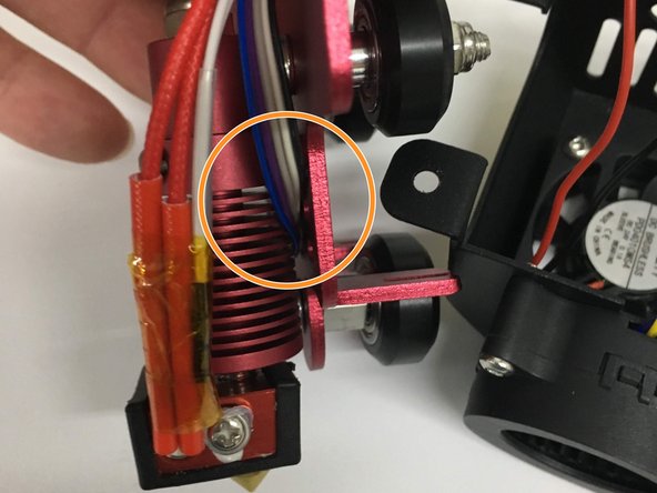
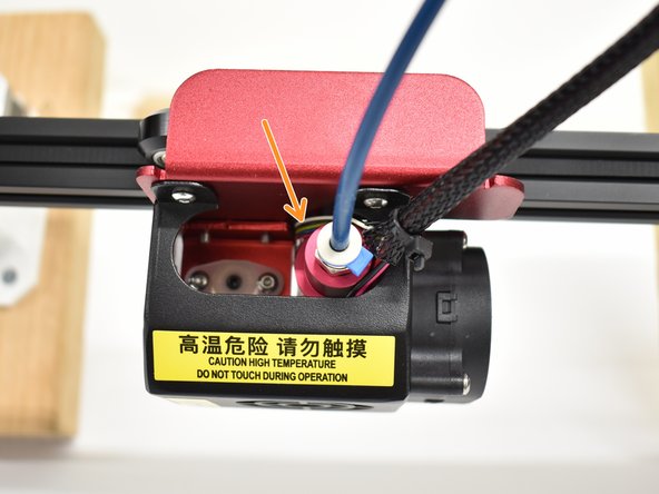
Führe auf der Seite des heißen Endes/der Sonde die Drähte hinter das heiße Ende und stecke sie in die Sonde.
-
Setze die Knopfkopfschrauben ein und ziehe sie fest.
-
-
-
-
Bringe einen neuen Kabelbinder an.
-
Verlege die BL-Touch-Leitungen wie gezeigt hinter dem heißen Ende.
-
Befestige den X-Träger wieder
-
Ziehe das untere Rad fest und befestige den Riemen wieder auf beiden Seiten (siehe Bilder in Schritt 1).
-
Bringe die vordere Lüfterabdeckung wieder an, achte dabei auf alle Leitungen.
-
Befestige die Bandenden wieder am X-Laufwerk
-
Schiebe die X-Achsen-Laufrolle nach rechts, um die Riemenspannung zu erhöhen, und ziehe die Innensechskantschrauben fest.
-
-
-
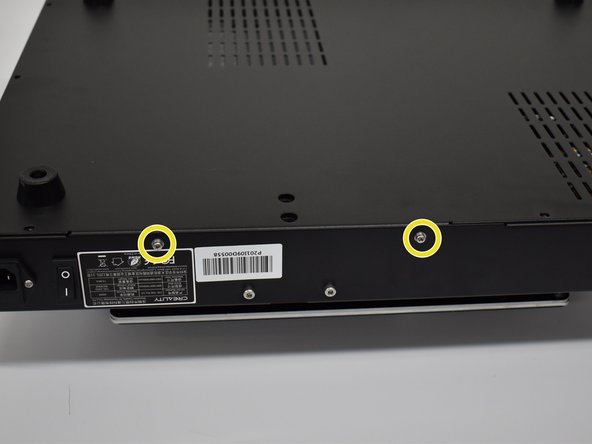
Entferne mit einem Kreuzschlitzschraubendreher Nr. #1 die 11 Schrauben an der Unterseite und 2 Schrauben an jeder Seite, insgesamt also 15. Entferne dann die untere Abdeckung.
-
Ziehe das Original-Flachbandkabel ab (nicht abgebildet)
-
Stecke neue Anschlüsse ein. Der Übersichtlichkeit halber werden hier nur die neuen Anschlüsse gezeigt.
-
Flachbandkabel (kodiert)
-
3-poliger schwarzer Stecker in D11 (Endreihe in Richtung SD-Kartensteckplatz) Orangefarbene Ader zeigt zum Flachbandkabel wie auf dem Bild.
-
2-poliger weißer Stecker in Z+ (Anschluss, der dem Flachbandkabel am nächsten ist) Aus der gleichen Sicht wie auf dem Bild, verwende die rechten 2 Stifte.
If not using a v2 pro do you need the jumper wire
No. Once you add a BL Touch per our guide, you will use V2 firmware from now on.
Hi, just so you know the placement of the red/brown connector in the image is wrong.
It needs to be connected to the Z- slot not the Z+ slot
No, please read our entire guide. It plugs into Z+ just like the CR-10S Pro V2 and CR-10 Max. The firmware determines which pin to use. Z+ is correct.
No, please read our entire guide. It plugs into Z+ just like the CR-10S Pro V2 and CR-10 Max. The firmware determines which pin to use. Z+ is correct.
What do you mean, “please read our entire guide”? If this page is the guide, where on this page does it say that Z+ determines which pin to use? The only reference on this page to Z+ is in this section above, to which Steven was referring. Is there another “guide”???
Hi what are the polarity of brown and red wires? of Z+ and the polarity of the 3 other wires?
-
-
-
Suche eine Micro-SD-Karte, die nicht größer als 16 GB ist, und formatiere sie auf FAT 32 / Standardbelegungsgröße.
-
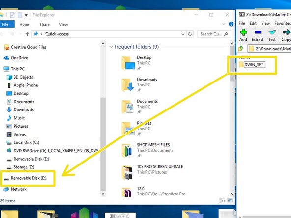
Lade die Screendateien herunter, entzippe sie und suche das Verzeichnis mit dem Namen "DWIN_SET". Diese Dateien sind in Schritt 12 ebenfalls verlinkt.
-
Benutze Kopieren/Einfügen, Ziehen oder Rechtsklick und Senden von DWIN_SET auf die formatierte SD-Karte.
DWIN_SET Not in Screen Files?
where can you find it
link does not work
Thanks - fixed.
I'm having trouble with the link here for that file to download.
the link for the screen files is dead. it will flash to a new window, then closes immediately
the link is not working something is wrong with it
yes i have the same problem. i cant download it :-(
With my Macs, the link are working.
It downloads TM3D_DWINCombinedScreens_V5.7z.
Try rigthclick with your mouse if it does not load.
Why does it state ""Default..." or 4096." if Default Allocation Size usually doesn't work? I assumed that was the correct first option to try since it was stated first, but it only works if it's set to 4096, NOT default.
I think it'd be better if it just said 4096. -
-
-
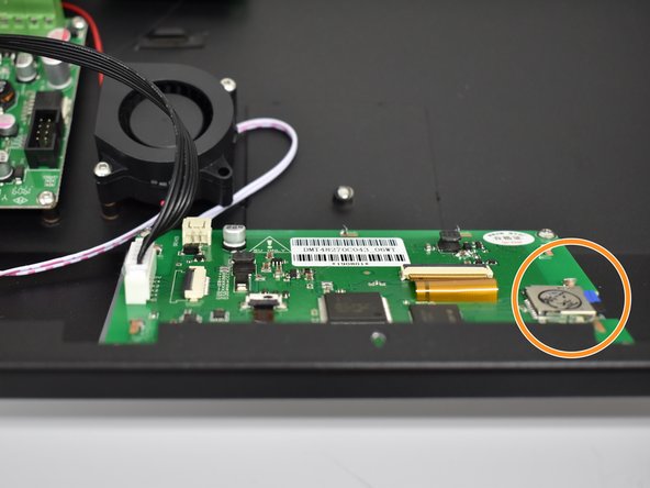
Stecke die korrekt konfigurierte sd-Karte in den Steckplatz am Display.
-
Vergewissere dich, dass der Netzschalter auf "0" steht, und schließe dann das Netzkabel an dein Gerät an. Stelle das Gerät so auf, dass du den Bildschirm sehen kannst, und schalte den Netzschalter ein.
-
Wenn alles richtig läuft, siehst du, wie die Dateien geladen werden, die Bilder blinken und dann oben "END" angezeigt wird. Siehe den nächsten Schritt für ein Video.
Ok great, what do we do with the sd card now? Remove it, leave it until after the next step? Can we turn the power off now?
See the next step.
all files appear as "Files: 0000; Download .CFG files: 0000, and images do not load, what should I do?
Probably incorrectly extracted the zip-archive or didn't extract at all..
Me falto ponerlo a 4096, saludos!
Optional: This is a good time to actually implement a small mod.
I applied this mod and am now able to flash the screen firmware from the outside of the printer:
-
-
-
Wenn alles richtig läuft, siehst du das Dateien geladen werden und es wird oben "END" angezeigt.
-
-
-
Stecke das Flachbandkabel oben ein, bis du spürst, dass die Clips auf beiden Seiten einrasten und die Verbindung verriegeln.
-
Stecke den 5-poligen Anschluss für BL-Touch Probe ein. Auch dieser Stecker hat eine Verriegelung, wenn er vollständig eingesteckt ist.
-
-
-
Schließe die USB-A-Seite an deinen Computer an.
-
Schließe die andere Seite des USB an deinen 3D-Drucker an.
-
FIRMWARE
-
Gehe auf http://bit.ly/2DIIXNi, um Dateien und Informationen zum Flashen der Firmware zu finden.
TM3D folks, the link above “http://bit.ly/2DIIXNi” goes to a gDoc, as you know, then on that gDoc is a link to the file that is at the URL “https://github.com/InsanityAutomation/Ma...
It downloads a file called - “TM3D_SingleExtruderDwin_V3.1.7z” which is consistent with the URL, so far so good …
Then on the gDoc you say - “Make sure the file name is SingleExtruderScreenDwin_V3.1.7z”
So, those are inconsistent.
That file expands to a folder called “DWIN_SET”. That folder has files in it that are consistent with what I believe they should be. I’m going to go with it assuming there’s a typo here or you shortened the file name due to path length limits or something like that. I’ll post back with results.
The links are correct - just the wording on the gdoc were not. Thank you for you letting us know. This has been corrected.
Thank you! Very much appreciated on a Sunday.
It appears to be working. Screen works. Audio is good. I’ve modified the location of the BL-Touch because of the Hemera conversion so I have to go change the offsets yet.
TM3D - You might want to change the link in step 8 here. It’s currently getting a 404. Obviously the link in this step works fine.
I can confirm the .WAV files get messed up by the in-built decompression utility in OS-X still. I’m on Catalina 10.15.7. So, I used “The Unarchiver“ app to decompress the 7-zip screen files ‘cause I just didn’t feel like messing with command line last night. After that & another re-flash of the screen all seems to be okay.
I used a 32GB micro SD. Works fine. Some of the earlier directions I ran into said “no more than 16GB”.
I used Prusa Slicer to upgrade the main board. I’ve used Cura in that past. So if Xloader is not working for someone there are options.
Igot the screen to flash. now when it boots, i get a machine fault warning with some chinese and it shows z, y and x axis is 0
Seems you didn't flash the motherboard then.
You need to do both for it to work.
hi,i flash diplay and fimware and i have on main screen "media init fail' what is it ? and how this problem fix ? thank you
Try to reboot the machine or press init sd card from print screen.
-
-
I have completed the install. The BLT is responsive at startup on my CR-10S Pro V1. When I auto home the Z does not stop descending even when the BLT triggers a touch. I have to cut the power before it just keeps going infinitely downward. I am not sure how to correct this. I am able to get all other functions to respond.
Ok, I made a super simple mistake, and I don’t want others to follow my path to frustration. I had accidentally grabbed the CR-10S Pro V1 firmware. Reading this over and over again it clicked that it said “you will use the V2 firmware going forward. I flashed in the new V2 firmware and all works perfectly. So don’t be a moron like me! lol
Sounds like you have a wiring to firmware mismatch - 2 pin connector should be connected to Z+ like shown in Step 7 and firmware for the CR-10S Pro V2 should be used.
Looks like you corrected it before we responded. Making a simple mistake is ok. We do link the firmware needed for this in the guide (Step 12)
My Z doesn’t move at all. When I hit leveling, it auto homes but the z never moves. The BLT plunges 4 or 5 times but nothing happens. (I’ve tried lots of other things with not luck)
-
-
Der Einrichtungsvorgang ist derselbe, AUSSER dass du keine Sondenhöhe oder Empfindlichkeit einstellen musst. Du musst nur deinen Z-Offset einstellen.
What if I've wired everything up correctly, checked it multiple times, and using my finger to activate the bl touch doesn't stop it?
I have a red + blue light on that's constant. The red light turns off when the hot end is lowering for homing, but never re-engages once the pin touches the bed and crashes. I am using the bl touch kit for cr10s pro.
I had the same issue. In my case I used the Z- firmware (listed as "CR10SPRO", without "V2").
I had connected the black/white wire to the correct port and used a jumper on the daughterboard.
What I had to do that eventually fixed it, was swap the black and white wire of the black/white connector and then everything was sorted.
-


Um dein Gerät wieder zusammenzubauen, folge den Schritte dieser Anleitung in umgekehrte Reihenfolge.
Um dein Gerät wieder zusammenzubauen, folge den Schritte dieser Anleitung in umgekehrte Reihenfolge.
Rückgängig: Ich habe diese Anleitung nicht absolviert.
5 weitere Nutzer:innen haben diese Anleitung absolviert.
Besonderer Dank geht an diese Übersetzer:innen:
100%


Diese Übersetzer:innen helfen uns, die Welt zu reparieren! Wie kann ich mithelfen?
Hier starten ›

Team

17 Kommentare
My LCD display got blank after turning on my printer once the display was flashed. I thought it would be fixed by the time I uploaded the hex.file but it didn't work. Now my printer is frozen and I dont know what to do. Is there an advice for this situation I will appreciate any help thank you!!
If you purchased the kit from Tiny Machines 3D, you can contact us directly at support@tinymachines3d.com
This guide is for customers but as it is public, it is open to all as reference. If you are having issues beyond that, check wiring.
So, does this mean that you would recommend that no one use your firmware upgrades unless they purchased their CR-10S Pro V2 from you? Unfortunately, I received my V2 before I learned of you guys and the very cool stuff you have done related to this printer (else, I definitely would have purchased from you). I was looking forward to upgrading with your firmware(s).
No, we don’t mean this at all. We want people to understand that there are some differences between our firmware and stock and the configuration outlined in the guide must be followed for the firmware to work correctly.
I had bought the BLTOUCH V3.1 with the jumper and the extension cable from you, but which firmware should I use now on my CR-10S PRO? that stock of Creality3d CR-10S PRO V2?
V2 and use Z+ port on the mainboard.
Hi Just completed this mod to my CR10s Pro (following the above instructions) The machine seems to be working OK, apart from the bed measuring feature If I hit the measuring icon the machine just freezes. and I have turn off the power to reset the printer.
Do you know of a fix for this problem ??
Hi - having the same issue. Did you ever figure this one out?
Watch our video. The system doesn’t freeze but rather starts a process when you press the “Measuring” button where it heats the bed, auto homes then starts probing 25 points. https://youtu.be/4ii58n5ha1s
but with this new upgrade I have to use the jumper on my CR-10S pro v1? can I use the Creality stock firmware for the CR-10s pro V2 even if I have the CR-10S pro V1, with this modification?
Did you get an answer to this question? I am wondering about the same thing. This post obviously refers to a CR-10S Pro V1 since the V2 already has the Bltouch. So I am assuming that the recommendation is to use the install the BLTouch to the port Z+ and no jumper and use the firmware for V2. Can someoen confirm it?
Mario -
If just installing the TM3D BL-Touch kit for the CR-10S Pro AND wiring it to the TM3D instructions, yes, use the TM3D firmware for V2. No you don’t use the jumper.
The bit about V1 to V2 is mentioned in the gDoc linked to in step 12 above. A link for the firmware hex file is also in the gDoc.
Functionally this switch makes your older V1 a V2, almost. Guessing the V2s probably have the 2.4.1 (or later) main board.
The one I converted is a CR-10S Pro -w- V 2.4 main board, dated 2018-8-13.
Tag on the screen board - DMT 48270C043_06WT. Also marked ZQ201903 (Machine purchased April, 2019)
Again the jumper at the Z- port on the ribbon cable breakout board, on the gantry, is NOT required with TM3D firmware & wiring scheme. TM3D is using the Z+ port on the main board. For some reason, that eliminates the need for the jumper.
IF you want to use the Creality firmware AND wiring scheme, that requires the jumper, as I understand it now. (Maybe that will change, I don’t know)
Hello, I would try your tuto but I have different color of cable. I try to look for a correspondance but notice that even on your picture it’s not ok. On step 4 the cable is “black / white / grey / violet / blue”. On the step 11 the same cable seems to be “white / black / yellow / blue / red”… (that’s the color I have in my kit). In this case, “white => green” and “black => yellow”. In my kit, “black an white” are the cable that goes to the place “brown and red” go on the motherboard … what a mess !!!
I have only one cable : on BL TOUCH => “white / black / yellow / blue / red” on MOTHERBOARD => white / black” // (“yellow / RED/ BLUE” (red and blue are interverted)
It should be great if you can put numbers (1-2-3-4-5) on BL Touch PIN and re-use those numbers on the motherboard… thanks
Fred
yes this was not clear to me either from the guide i had to use some guess work on this to work out the same
There are no Files available. Can you please fix it, so I can use mit BL Touch kit?
Keep all screws as they will be reused during assembly.
Note how the X-Axis Belt is positioned before removing belt ends from carriage.
Do not fully remove the X-Axis Belt
Joel Gabel - Antwort
Revised, remove your comment if you agree.
Tiny Machines 3D - Antwort
Orange step - “UNTIL THE…” Until the What? This sentence wasn’t finished. Thanks.
johnyringo83 - Antwort