Einleitung
This guide will help you replace the motherboard of your camera.
Be sure to use a magnetic mat or container to hold small screws. Keeping your screws organized will help you return them to their designated holes during reassembly.
Was du brauchst
-
-
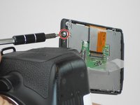
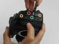
Take the LCD out of its place to expose the Phillips #PH00 screws.
-
Remove the two 2.5 mm Phillips #PH00 black screws on both sides of the LCD screen.
-
Next remove the two 3 mm Phillips #PH00 black screws near both sides of the base where the screen swivels.
-
-
-
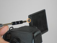
Remove the 3 mm Phillips #PH00 silver screw on the side of the screen.
-
Turn the screen to remove the second 3 mm Phillips #PH00 silver screw.
-
-
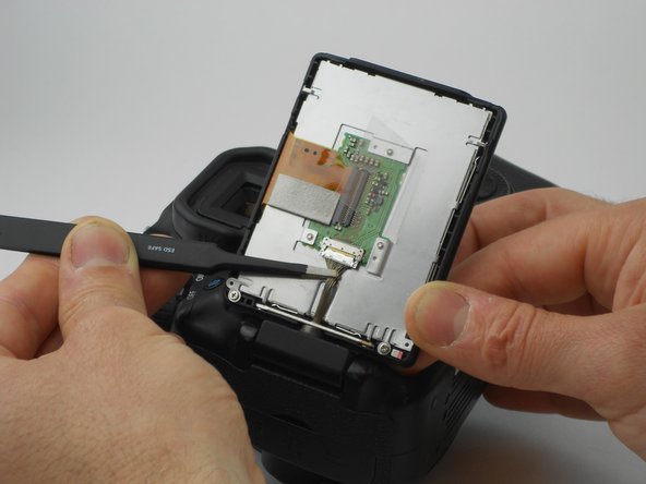
In diesem Schritt verwendetes Werkzeug:Tweezers$4.99
-
Using the tweezers, carefully disconnect the rear connector by pulling it away from the screen.
-
-
-
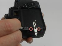
Now, four 2.2 mm Phillips #PH00 screws holding a cover around the hinge should be visible.
-
Turn the swivel around to expose the remaining of the aforementioned screws.
-
Then use the PH00 screw driver to remove them.
-
-
-
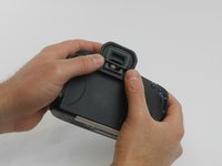
The eye piece will slide right off with a firm push upwards.
-
Remove the 3.4 mm Phillips #PH00 screw using a PH00 screw driver.
-
Remove the two 9.9 mm Phillips #PH00 screws using the PH00 screwdriver.
-
-
-
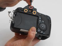
Using the PH00 screwdriver, remove the 3.8 mm Phillips #PH00 screw located on the back of the camera.
-
-
-
-
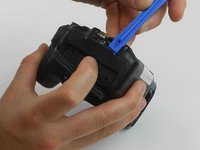
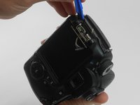
Using the plastic opening tool, carefully pull up the rubber grip around the port side of the camera.
-
Remove the four different sized screws located beneath the rubber grip.
-
6 mm Phillips #PH00 screw.
-
3.4 mm Phillips #PH00 screw.
-
3.9 mm Phillips #PH00 screw.
-
2.2 mm Phillips #PH00 screw.
-
-
-
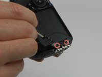
Remove two 4.8 mm Phillips #PH00 screws from the memory card side of camera using the PH00 screwdriver.
-
-
-
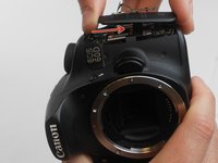
Look at the bottom of the camera so the serial number tag reads up right.
-
Using the PH00 screw driver, remove the top three 3.5 mm Phillips #PH00 screws.
-
-
-
Now gently pull the back cover off the camera.
-
Gently pull the orange wire connected to the motherboard of the camera up and off of the motherboard.
-
-
-
Carefully pry off the LCD screen connector up from the motherboard to disconnect it, using the plastic opening tool.
-
-
-
Remove one 2.8 mm Phillips #PH00 black screw on the side of the swivel assembly by using the PH00 screwdriver.
-
-
-
Remove the two 2.8 mm Phillips #PH00 black screws on the back of the swivel assembly using the PH00 screwdriver.
-
-
-
Remove the two 4.4 mm Phillips #PH00 screws holding the silver cover using the PH00 screwdriver.
-
Next lift the cover off of the motherboard.
-
-
-
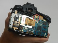
Use a plastic opening tool to lift the small hinge holding the circled gold ribbon in place, then gently slide the ribbon out of the socket.
-
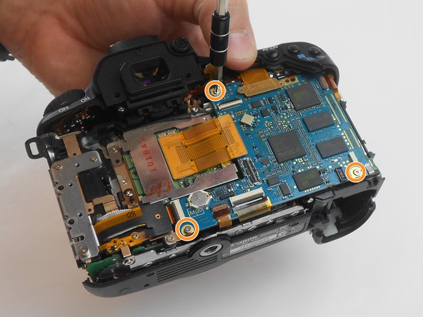
Next unscrew the three 4.3 mm Phillips #PH00 screws holding the motherboard down using the PH00 screwdriver.
-
-
In diesem Schritt verwendetes Werkzeug:Tweezers$4.99
-
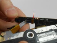
Next the wires are able to come off.
-
The RED arrows indicate a small hinge locking the wire in. To remove the wire, follow the same steps taken to remove the wire in the prior steps.
-
The ORANGE markers indicate that you need to lift the wire up and off of the motherboard. Using the opening tool, follow the same steps used to remove the swivel screen wire.
-
Next it is recommended that you use tweezers to carefully remove all hinged wires as demonstrated by the YELLOW arrow on the second image in this step.
-
-
-
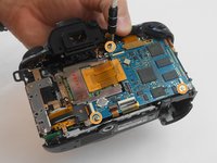
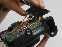
With the motherboard lifted, remove the indicated wire by using a plastic opening tool.
-
With the first bottom wire removed, the motherboard can be lifted higher, showing two more hidden wires.
-
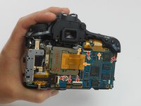
Remove the wire indicated by the ORANGE arrow by undoing a hinge and sliding the wire out.
-
Remove the wire indicated by the YELLOW arrow by gently pulling it straight out of the socket it is seated in.
-
-
-
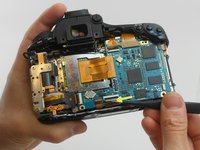
With every wire properly removed, the motherboard can now be lifted out of the camera.
-


To reassemble your device, follow these instructions in reverse order.
To reassemble your device, follow these instructions in reverse order.
Rückgängig: Ich habe diese Anleitung nicht absolviert.
14 weitere Personen haben diese Anleitung absolviert.
Team

USF Tampa, Team 16-6, Wollert Fall 2015 Mitglied von USF Tampa, Team 16-6, Wollert Fall 2015
USFT-WOLLERT-F15S16G6
3 Mitglieder
14 Anleitungen geschrieben
3 Kommentare
Dear Tyler, there is no need to remove the lcd, the camera can be easily repared by removing the back cover and than loosening the conectors and replacing the motherboard,there is no use in removing the lcd.