Diese Version enthält möglicherweise inkorrekte Änderungen. Wechsle zur letzten geprüften Version.
Was du brauchst
-
Dieser Schritt ist noch nicht übersetzt. Hilf mit, ihn zu übersetzen!
-
Remove the two 7.9 mm screws using a Phillips #1 screwdriver.
-
-
Dieser Schritt ist noch nicht übersetzt. Hilf mit, ihn zu übersetzen!
-
Lift up the back cover to remove it.
-
-
-
Dieser Schritt ist noch nicht übersetzt. Hilf mit, ihn zu übersetzen!
-
Remove the blue lever from its slot by pushing it back and twisting clockwise.
-
Close the scanner compartment and cover.
-
-
Dieser Schritt ist noch nicht übersetzt. Hilf mit, ihn zu übersetzen!
-
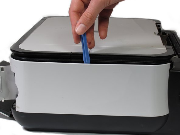
Pry open the side cover with the plastic opening tool.
-
-
Dieser Schritt ist noch nicht übersetzt. Hilf mit, ihn zu übersetzen!
-
Flip the printer over so that the bottom of the printer is facing you.
-
Use the plastic opening tool to remove the corner of the side panel from the plastic pin.
-
-
Dieser Schritt ist noch nicht übersetzt. Hilf mit, ihn zu übersetzen!
-
Use the plastic opening tool to loosen the side panel from the bottom of the printer.
-
-
Dieser Schritt ist noch nicht übersetzt. Hilf mit, ihn zu übersetzen!
-
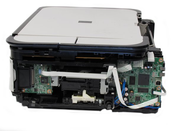
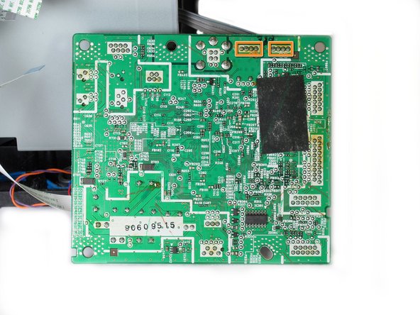
Gently pull the 6 ribbon wires out.
-
Gently pull the 4 molded cable assemblies out.
-
-
Dieser Schritt ist noch nicht übersetzt. Hilf mit, ihn zu übersetzen!
-
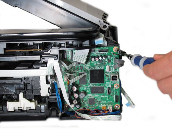
Unscrew the five silver Phillips screws that secure the motherboard:
-
Five 3.65mm Phillips #1 screws.
-
-
Dieser Schritt ist noch nicht übersetzt. Hilf mit, ihn zu übersetzen!
-
Once all wires and screws have been removed, gently take the motherboard out of the printer.
-
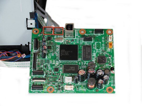
These wires are soldered onto the bottom of the PCB and must be de-soldered in order to completely detach the motherboard from the printer.
-
De-solder these eight solder joints on the bottom of the motherboard.
-
When reinstalling the motherboard back into the printer, solder the highlighted joints (in orange markers in the second photo) back onto the board.
-


Rückgängig: Ich habe diese Anleitung nicht absolviert.
3 weitere Nutzer:innen haben diese Anleitung absolviert.
Team

Cal Poly, Team 19-41, Regan Winter 2013 Mitglied von Cal Poly, Team 19-41, Regan Winter 2013
CPSU-REGAN-W13S19G41
4 Mitglieder
6 Anleitungen geschrieben