Diese Version enthält möglicherweise inkorrekte Änderungen. Wechsle zur letzten geprüften Version.
Was du brauchst
-
Dieser Schritt ist noch nicht übersetzt. Hilf mit, ihn zu übersetzen!
-
Slide the switch on the battery cover labeled "CARD/BATT. OPEN." to the right.
-
While still holding the switch, pull the cover down, allowing it to release and open.
-
-
Dieser Schritt ist noch nicht übersetzt. Hilf mit, ihn zu übersetzen!
-
Tilt the camera slightly to allow the batteries to fall out.
-
-
Dieser Schritt ist noch nicht übersetzt. Hilf mit, ihn zu übersetzen!
-
Press on and release the memory card to eject it.
-
-
Dieser Schritt ist noch nicht übersetzt. Hilf mit, ihn zu übersetzen!
-
Unscrew the 5mm Phillips #00 screw from the bottom of the camera.
-
-
Dieser Schritt ist noch nicht übersetzt. Hilf mit, ihn zu übersetzen!
-
Unscrew the three 2mm Phillips #00 screws that are located on the bottom of the camera.
-
-
Dieser Schritt ist noch nicht übersetzt. Hilf mit, ihn zu übersetzen!
-
Remove the 4mm Phillips #00 screw that is located on the left side of the camera, if the display screen is facing you.
-
-
Dieser Schritt ist noch nicht übersetzt. Hilf mit, ihn zu übersetzen!
-
Take out the 4mm Phillips #00 screw under the rubber flap on the right end of the camera.
-
-
Dieser Schritt ist noch nicht übersetzt. Hilf mit, ihn zu übersetzen!
-
Remove the second battery cover on the bottom of camera.
-
Take the silver battery out of the camera.
-
-
Dieser Schritt ist noch nicht übersetzt. Hilf mit, ihn zu übersetzen!
-
Remove the 4mm Phillips #00 screw on the inside of the flap that hides the battery and memory card slots.
-
Remove the light grey, plastic piece.
-
Remove the plastic portion of the battery flap cover. The metal piece will remain attached.
-
-
-
Dieser Schritt ist noch nicht übersetzt. Hilf mit, ihn zu übersetzen!
-
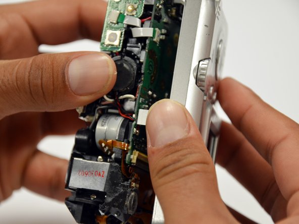
Slightly pull on each side of the camera. It should loosen up and come apart.
-
If it does not pull apart right away, use a little more force.
-
Do not give up!
-
-
Dieser Schritt ist noch nicht übersetzt. Hilf mit, ihn zu übersetzen!
-
Remove the back case of the camera by pulling from the top.
-
-
Dieser Schritt ist noch nicht übersetzt. Hilf mit, ihn zu übersetzen!
-
Remove the 4mm Phillips #00 screw from above the ribbon.
-
-
Dieser Schritt ist noch nicht übersetzt. Hilf mit, ihn zu übersetzen!
-
Gently peel off the blue tape on the top of the LCD screen.
-
-
Dieser Schritt ist noch nicht übersetzt. Hilf mit, ihn zu übersetzen!
-
Remove the 4mm Phillips #00 screw previously concealed by the blue tape.
-
-
Dieser Schritt ist noch nicht übersetzt. Hilf mit, ihn zu übersetzen!
-
Gently lift the LCD screen off of the front casing by pulling up a tab on the side of the camera.
-
-
Dieser Schritt ist noch nicht übersetzt. Hilf mit, ihn zu übersetzen!
-
Using a spudger, lift the grey tabs to allow the ribbon to slide out.
-
-
Dieser Schritt ist noch nicht übersetzt. Hilf mit, ihn zu übersetzen!
-
Since the tabs have been lifted, the ribbon should now slide out out easily.
-
-
Dieser Schritt ist noch nicht übersetzt. Hilf mit, ihn zu übersetzen!
-
Remove the 5mm Phillips #00 screw located above the small black piece on the right side of the mother board.
-
-
Dieser Schritt ist noch nicht übersetzt. Hilf mit, ihn zu übersetzen!
-
Remove the 4mm Phillips #00 screw at the bottom of the black piece.
-
Detach the black piece that the screws previously held in place.
-
-
Dieser Schritt ist noch nicht übersetzt. Hilf mit, ihn zu übersetzen!
-
Remove the 5mm Phillips #00 screw in the middle of the motherboard.
-
-
Dieser Schritt ist noch nicht übersetzt. Hilf mit, ihn zu übersetzen!
-
Remove the 5mm Phillips #00 screw that holds the metal piece to the bottom of the camera .
-
-
Dieser Schritt ist noch nicht übersetzt. Hilf mit, ihn zu übersetzen!
-
Remove the 5mm Phillips #00 screw that is located on the top of camera.
-
-
Dieser Schritt ist noch nicht übersetzt. Hilf mit, ihn zu übersetzen!
-
Remove the 2mm Phillips #00 screw that is located on the far left of the motherboard.
-
-
Dieser Schritt ist noch nicht übersetzt. Hilf mit, ihn zu übersetzen!
-
Remove the 5mm Phillips #00 screw near the bottom left of the motherboard.
-
-
Dieser Schritt ist noch nicht übersetzt. Hilf mit, ihn zu übersetzen!
-
Using a spudger, unlock the locking mechanism that holds the lower orange ribbon in place.
-
Once unlocked, slide out the ribbon.
-
-
Dieser Schritt ist noch nicht übersetzt. Hilf mit, ihn zu übersetzen!
-
Using a spudger, unlock the locking mechanism that holds the upper orange ribbon in place.
-
Once unlocked, slide out the ribbon.
-
-
Dieser Schritt ist noch nicht übersetzt. Hilf mit, ihn zu übersetzen!
-
All that is required is to unsolder the few remaining wires. Then, the motherboard will be ready to be replaced!
-


Rückgängig: Ich habe diese Anleitung nicht absolviert.
2 weitere Nutzer:innen haben diese Anleitung absolviert.
Team

Cal Poly, Team 19-42, Regan Winter 2013 Mitglied von Cal Poly, Team 19-42, Regan Winter 2013
CPSU-REGAN-W13S19G42
4 Mitglieder
12 Anleitungen geschrieben