Diese Version enthält möglicherweise inkorrekte Änderungen. Wechsle zur letzten geprüften Version.
Was du brauchst
-
Dieser Schritt ist noch nicht übersetzt. Hilf mit, ihn zu übersetzen!
-
Open the battery flap on the bottom of the camera by applying pressure and pushing in the direction of the arrow.
-
Remove your finger and allow the flap to pop open.
-
-
Dieser Schritt ist noch nicht übersetzt. Hilf mit, ihn zu übersetzen!
-
Push the brown lever so that it pivots counterclockwise.
-
Grip and remove the battery.
-
-
Dieser Schritt ist noch nicht übersetzt. Hilf mit, ihn zu übersetzen!
-
Remove the ring around the lens by simultaneously pressing the black button located at the bottom right of the ring and rotating the ring counterclockwise.
-
-
Dieser Schritt ist noch nicht übersetzt. Hilf mit, ihn zu übersetzen!
-
Remove the four 3.3 mm screws on the bottom of the camera using a Phillips #00 screwdriver.
-
-
Dieser Schritt ist noch nicht übersetzt. Hilf mit, ihn zu übersetzen!
-
Remove the 3.3 mm screw on the right side of the viewfinder using a Phillips #00 screwdriver.
-
-
Dieser Schritt ist noch nicht übersetzt. Hilf mit, ihn zu übersetzen!
-
Remove the two 3.3 mm screws near the speaker using a Phillips #00 screwdriver.
-
-
-
Dieser Schritt ist noch nicht übersetzt. Hilf mit, ihn zu übersetzen!
-
Open the port cover by lifting up the tab with your finger and remove the 3.3 mm screw underneath the cover using a Phillips #00 screwdriver.
-
Remove the other 3.3 mm screw below the ports using a Phillips #00 screwdriver.
-
-
Dieser Schritt ist noch nicht übersetzt. Hilf mit, ihn zu übersetzen!
-
Using your fingers, carefully pull the the back cover off by grabbing the bottom left of the back cover and pulling outwards.
-
-
Dieser Schritt ist noch nicht übersetzt. Hilf mit, ihn zu übersetzen!
-
Using your fingers, carefully pry the front cover off starting at the bottom right.
-
-
Dieser Schritt ist noch nicht übersetzt. Hilf mit, ihn zu übersetzen!
-
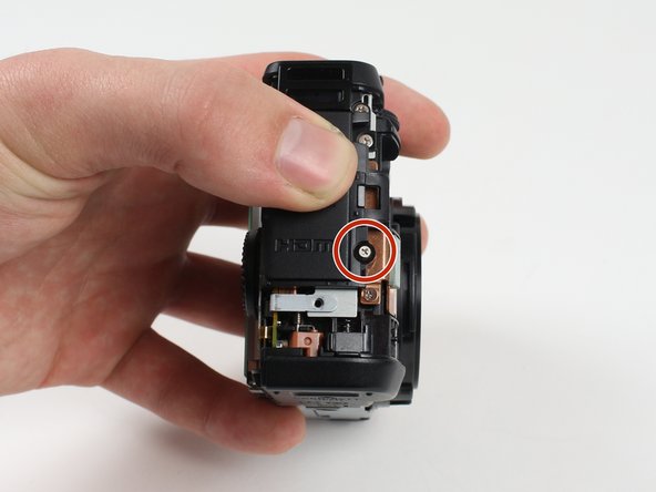
Remove the 3.8 mm screw at the bottom right of the port cover housing using a Phillips #00 screwdriver.
-
Lift away the port cover housing.
-
-
Dieser Schritt ist noch nicht übersetzt. Hilf mit, ihn zu übersetzen!
-
Reorient the camera so that you are looking at the back.
-
Unplug the button circuit board from the motherboard by unlocking the ZIF connector (gently lift the brown lock that keeps the cable in place).
-
Pull the connector downwards with the tweezers.
-
-
Dieser Schritt ist noch nicht übersetzt. Hilf mit, ihn zu übersetzen!
-
Remove the 3.0 mm screw on the top of the button memory board using a Phillips #00 screwdriver.
-
Remove the 2.8 mm screw on the bottom of the button memory board using a Phillips #00 screwdriver.
-
-
Dieser Schritt ist noch nicht übersetzt. Hilf mit, ihn zu übersetzen!
-
Lift the button circuit board away from the camera.
-
-
Dieser Schritt ist noch nicht übersetzt. Hilf mit, ihn zu übersetzen!
-
Unlock the ZIF connector for the large connector ribbon by lifting up on the brown flap with the plastic opening tool.
-
Gently pull the connector straight out of the housing with your fingers.
-
-
Dieser Schritt ist noch nicht übersetzt. Hilf mit, ihn zu übersetzen!
-
Unplug the small connector ribbon by pulling the cable outwards from the camera using a spudger or your fingers.
-
-
Dieser Schritt ist noch nicht übersetzt. Hilf mit, ihn zu übersetzen!
-
Gently lift the LCD away from the camera housing.
-


Rückgängig: Ich habe diese Anleitung nicht absolviert.
7 weitere Nutzer:innen haben diese Anleitung absolviert.

Team

Cal Poly, Team 70-6, Forte Winter 2016 Mitglied von Cal Poly, Team 70-6, Forte Winter 2016
CPSU-FORTE-W16S70G6
4 Mitglieder
7 Anleitungen geschrieben
8 Kommentare
1) Step 11 needs to be updated
2) Add Tweezers to the "tools needed" part at the beginning
Otherwise nice instruction
Nice set of instructions, although I had a real problem at step 11, and I recommend it be updated.
The instructions for step 14 should be copied-and-pasted into step 11.
Looking at the instructions for step 11, it was not at all clear that the brown lock-flap needed to be lifted first, and that the connector would then come out quite easily. Applying tweezers to the connector without first knowing about the brown lock-flap could easily lead to damaging the ribbon cable, as almost happened in my case.
So, for anyone reading this (in case the instruction set is not updated by the author), use the instructions for step 14 when you are at step 11. The connector will come out easily after the brown lock-flap is lifted, and the "connector" is NOT the grey plastic part that you see; it is in fact simply the end of the ribbon cable.
Thank You to the author. This instruction set saved me a bunch of money.
Also about step 11: Twezers may harm the cable. After opening the brown lock you can just carefully let the cable get out on step 13 while lifting the button circuit board away from the camera. On the reverse order,after replacement, twezers are needed to push the cable gently in.
Great instructions and comments, a real help however any ideas where I can get a good quality LCD please?