Diese Version enthält möglicherweise inkorrekte Änderungen. Wechsle zur letzten geprüften Version.
Was du brauchst
-
Dieser Schritt ist noch nicht übersetzt. Hilf mit, ihn zu übersetzen!
-
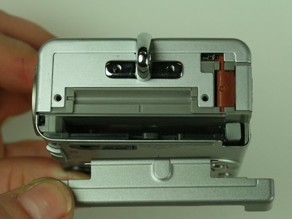
On the backside of the camera, remove the 4.75 mm screw that sits at the top right corner.
-
Remove the four 4.75 mm screws that sit at the bottom of the camera.
-
-
Dieser Schritt ist noch nicht übersetzt. Hilf mit, ihn zu übersetzen!
-
On the side of the camera, remove the two 4.75 mm screws that sit near the USB digital terminal.
-
-
Dieser Schritt ist noch nicht übersetzt. Hilf mit, ihn zu übersetzen!
-
On the side of the camera, remove the four 4.75 mm screws that sit near the wrist strap mount.
-
Remove the two small metal plates, which the four screws hold in place.
-
-
-
Dieser Schritt ist noch nicht übersetzt. Hilf mit, ihn zu übersetzen!
-
Remove the small black plastic piece and set it aside. If necessary, use tweezers to remove the small black plastic piece.
-
Detach the front case and back case.
-
-
Dieser Schritt ist noch nicht übersetzt. Hilf mit, ihn zu übersetzen!
-
Remove the 3.5 mm screw that sits on the metal plate at the bottom of the camera.
-
Remove the two other 3.5 mm screws that sit on the side, to the left of the screw you just removed.
-
-
Dieser Schritt ist noch nicht übersetzt. Hilf mit, ihn zu übersetzen!
-
A ribbon cable attaches to the metal plate and to the main circuit board, on the front of the camera.
-
Gently release the black latch.
-
Remove the ribbon cable and metal plate assembly.
-
-
Dieser Schritt ist noch nicht übersetzt. Hilf mit, ihn zu übersetzen!
-
On the backside of the camera, remove the 3.5 mm screw that sits to the left of the viewfinder and above the LCD screen.
-
Remove the second 3.5 mm screw that sits directly above the LCD screen.
-
Gently detach the ribbon cable.
-
-
Dieser Schritt ist noch nicht übersetzt. Hilf mit, ihn zu übersetzen!
-
Locate the ribbon cable on the main circuit board, which sits below the lens.
-
Gently release the black latch on the ribbon cable connector and detach the ribbon cable.
-
-
Dieser Schritt ist noch nicht übersetzt. Hilf mit, ihn zu übersetzen!
-
Remove the LCD screen and set it aside.
-


Rückgängig: Ich habe diese Anleitung nicht absolviert.
Ein:e weitere:r Nutzer:in hat diese Anleitung absolviert.
Team

Cal Poly, Team 5-19, Amido Winter 2011 Mitglied von Cal Poly, Team 5-19, Amido Winter 2011
CPSU-AMIDO-W11S5G19
4 Mitglieder
6 Anleitungen geschrieben