Diese Version enthält möglicherweise inkorrekte Änderungen. Wechsle zur letzten geprüften Version.
Was du brauchst
-
Dieser Schritt ist noch nicht übersetzt. Hilf mit, ihn zu übersetzen!
-
Turn the printer over.
-
Use the PH1 screw bit to remove the three 8 mm screws in the middle of the back plate.
-
-
Dieser Schritt ist noch nicht übersetzt. Hilf mit, ihn zu übersetzen!
-
Loosen up the four 10 mm corner screws.
-
-
Dieser Schritt ist noch nicht übersetzt. Hilf mit, ihn zu übersetzen!
-
Turn the device around and remove the "open" lid.
-
Gently bend the lid and remove it from its hinges.
-
-
-
Dieser Schritt ist noch nicht übersetzt. Hilf mit, ihn zu übersetzen!
-
Turn the device back over and lift the top panel up.
-
Disconnect the ribbon cables leading to the LCD screen.
-
Pull the top panel off.
-
-
Dieser Schritt ist noch nicht übersetzt. Hilf mit, ihn zu übersetzen!
-
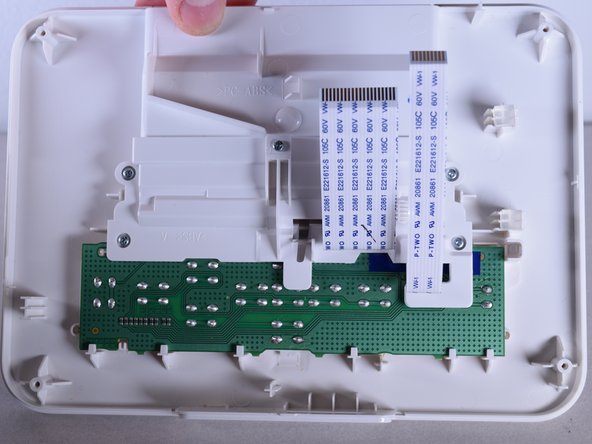
Turn the top panel over so the inside faces toward you.
-
-
Dieser Schritt ist noch nicht übersetzt. Hilf mit, ihn zu übersetzen!
-
Use the PH0 screw bit to remove the five 10 mm screws located above the circuit board.
-
-
Dieser Schritt ist noch nicht übersetzt. Hilf mit, ihn zu übersetzen!
-
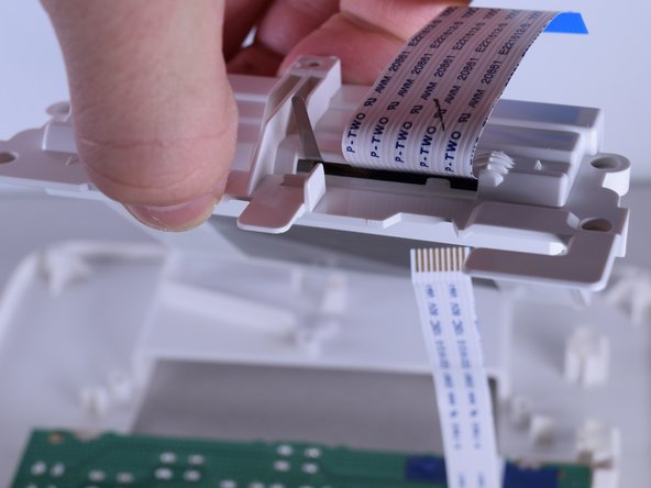
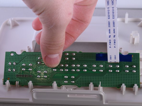
Carefully remove the frame attached to the screen.
-
-
Dieser Schritt ist noch nicht übersetzt. Hilf mit, ihn zu übersetzen!
-
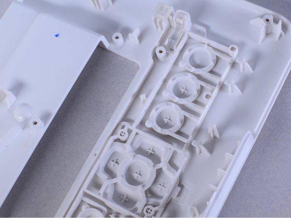
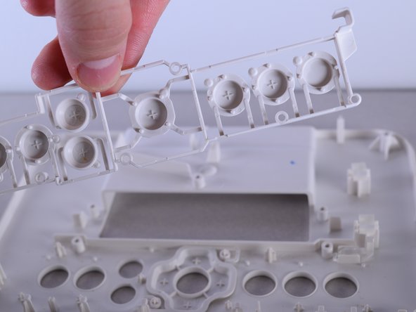
Remove the button framework and replace it with new one.
-


Team

UW Tacoma, Team 1-6, Rose Winter 2016 Mitglied von UW Tacoma, Team 1-6, Rose Winter 2016
UWT-ROSE-W16S1G6
4 Mitglieder
10 Anleitungen geschrieben