Einleitung
A failure on the "Delivered Volume Test" can signify dirty filters needing replacement. Knowing how to replace these is vital to the Ventilator's function. This guide will run through all the necessary steps including the removal of the:
-Power cable
-Top Panel
-Battery Tray
-Left Panel
-Blender Assembly
And finally the Turbine/Muffler Assembly itself
Was du brauchst
-
Schritt 1 Cardinal Health Vela Ventilator Power Cable Removal
Achtung: Die Schritte 1-2 stammen von einer Anleitung, die derzeit bearbeitet wird.
-
Use a screwdriver to remove the two Phillips pan-head screws at the top of the plug guard.
-
-
-
Remove the four Phillips #0 screws on the back side of the ventilator.
-
-
-
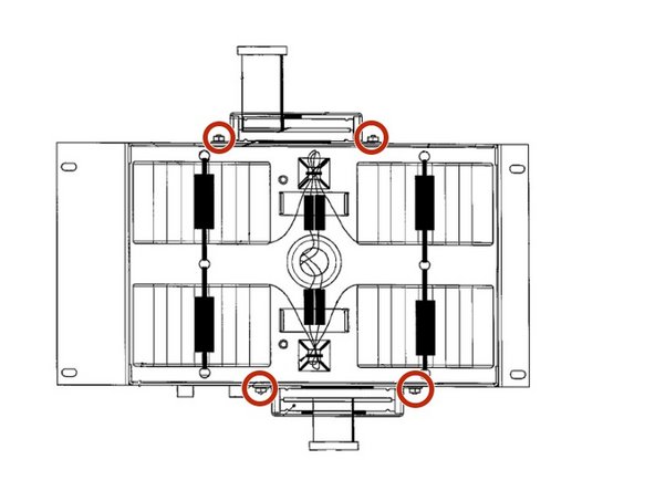
Remove all six small side panel screws along the bottom of each side of the top cover with the same screwdriver.
-
-
Schritt 6 Cardinal Health Vela Ventilator Battery Tray Removal
Achtung: Die Schritte 6-8 stammen von einer Anleitung, die derzeit bearbeitet wird.
-
Use your Phillips screwdriver to unscrew the 4 Phillips pan head screws positioned on each side of the battery tray.
-
-
-
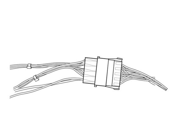
Disconnect the batteries from the ventilator by pulling apart the Battery Connector.
-
-
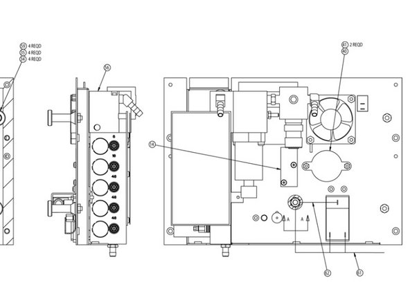
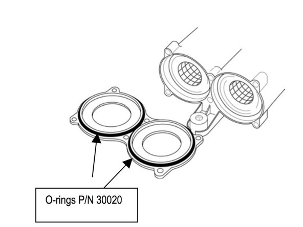
Schritt 13 Blender Assembly P/N 16358A
Achtung: Die Schritte 13-21 stammen von einer Anleitung, die derzeit bearbeitet wird.
-
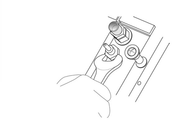
If the rear panel is installed, remove the high and low pressure oxygen fittings from the rear panel using your 3/4" wrench. NOTE: the high pressure fitting is located above the low pressure fitting
-
-
-
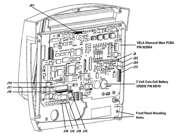
If the rear panel is installed, disconnect the 40-pin ribbon cable from the SVGA out PCB.
-
-
-
Disconnect the:
-
-J301, 12-Pin Connector to J301 on the main PCB
-
From the blender PCB
-
-
-
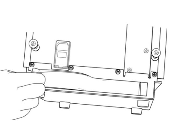
Remove the bottom strip ambient air inlet filter by pinching and pulling it out.
-
-
-
Remove the three Phillips pan-head screws on the right side of the rear panel.
-
-
-
The assembly should now be free to remove. As you remove the unit use your needle-nose pliers to disconnect the oxygen diffuser tube as you remove the blender assembly.
-
-
-
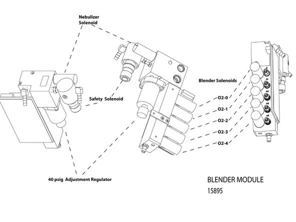
If the exhalation valve assembly is installed, disconnect:
-
J3 [2-pin (blue connection)]
-
To the oxygen inlet solenoid on the blender assembly.
-
J4 [2-pin (red connection)]
-
To the Nebulizer solenoid assembly on upper rear of blender.
-
-
-
Disconnect the main wire harness connector at P2 on the Turbine Driver PCBA
-
-
-
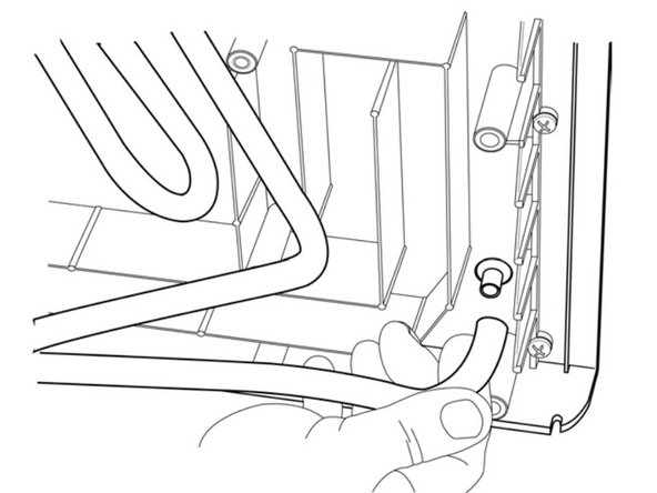
Disconnect the gray silicone intake and output elbows by gently pulling them out from the muffler tubes.
-
-
-
The Turbine/Muffler Assembly should now be free to lift off the manifold base.
-
Gently pull up on the elbows to remove
-
-
-
To Install P/N 16350 "Turbine/Muffler Assembly" repeat the steps in reverse order.
-
-
-
Remove the six Phillips pan-head screws on the cover of the filter
-
-
-
Use your needle-nose pliers to remove the left and right filter assemblies. The right filter should have a "filter sock" on it.
-
-
-
To Install follow the steps in reverse order. If you are replacing the P/N 10365 muffler/filter assemblies then, make sure to place the muffler (output) in the left tube and the sock filter (input) in the right tube.
-


To reassemble your device, follow these instructions in reverse order.
To reassemble your device, follow these instructions in reverse order.
Team

Cal Poly, Team S7-G22, Paton Spring 2020 Mitglied von Cal Poly, Team S7-G22, Paton Spring 2020
CPSU-PATON-S20S7G22
1 Mitglied
3 Anleitungen geschrieben