Diese Version enthält möglicherweise inkorrekte Änderungen. Wechsle zur letzten geprüften Version.
Was du brauchst
-
Dieser Schritt ist noch nicht übersetzt. Hilf mit, ihn zu übersetzen!
-
Three 3/8" standard Phillips screws
-
And one 3/8" non-standard triangular Phillips screw.
-
-
Dieser Schritt ist noch nicht übersetzt. Hilf mit, ihn zu übersetzen!
-
Remove the "K" rubber pad, then remove the three 3/8" Phillips screws from the baseplate using a #1 Phillips screwdriver.
-
Remove the non-standard Phillips screw.
-
-
Dieser Schritt ist noch nicht übersetzt. Hilf mit, ihn zu übersetzen!
-
Ensure that the cord is completely unwound from the base plate.
-
Lift the base plate away from the unit.
-
-
Dieser Schritt ist noch nicht übersetzt. Hilf mit, ihn zu übersetzen!
-
Carefully lift the red square protector off the post holding it in place.
-
-
Dieser Schritt ist noch nicht übersetzt. Hilf mit, ihn zu übersetzen!
-
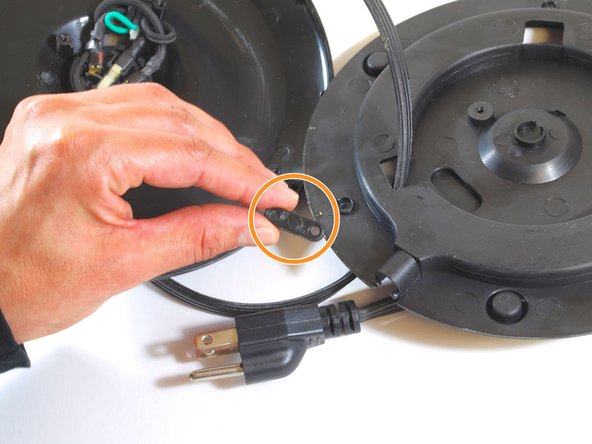
Remove the two 3/8" Phillips screws using a #1 Phillips screwdriver.
-
Remove the clamp which holds the cord in place.
-
-
Dieser Schritt ist noch nicht übersetzt. Hilf mit, ihn zu übersetzen!
-
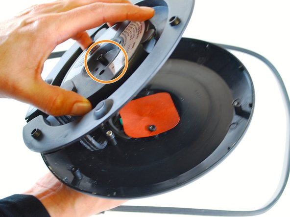
Use your hands to pull the black cylinder out from the center of the baseplate. This is the power coupling.
-
The GREEN wire is the 'ground' or 'protection' wire. It is connected to the center post.
-
The other two wires are both BLACK. You can distinguish them by feel:
-
The smooth wire is the 'neutral' wire.
-
The ribbed wire is the 'hot' wire.
-
-
-
Dieser Schritt ist noch nicht übersetzt. Hilf mit, ihn zu übersetzen!
-
Remove the connectors (spaded lugs) from the kettle's power coupling by gently pulling on each wire.
-
-
Dieser Schritt ist noch nicht übersetzt. Hilf mit, ihn zu übersetzen!
-
You will need three 16-22 gauge connectors (spaded lugs). The 'gauge' number refers to the wire size the lug connector is designed to fit. These connectors will slip over the contacts on the power coupling.
-
-
Dieser Schritt ist noch nicht übersetzt. Hilf mit, ihn zu übersetzen!
-
On the replacement cord, remove the white, green, and black protective caps. By hand, affix one connector to each cord wire. Follows these steps for each wire:
-
Twist the copper strands on the wire so you can cleanly insert the wire into the connector.
-
Push the copper wiring into the connector until the insulation prevents further insertion.
-
-
Dieser Schritt ist noch nicht übersetzt. Hilf mit, ihn zu übersetzen!
-
Using the multi-tool in crimper mode (or a special crimping tool), apply pressure on the connector 'shank' where the wire was inserted.
-
The ridge that you achieve by crimping should look the same as the connector shown here on the green wire. Give the connector a gentle pull to confirm it is well connected to the wire (it should not slip off).
-
Repeat steps 10 and 11 for the remaining two wires requiring connectors.
-
-
Dieser Schritt ist noch nicht übersetzt. Hilf mit, ihn zu übersetzen!
-
Thread the replacement cord through the opening closest to the cord symbol on the bottom of the baseplate.
-
Insert the cord until the green, white, and black wires are pushed all the way through.
-
-
Dieser Schritt ist noch nicht übersetzt. Hilf mit, ihn zu übersetzen!
-
Reinsert the power coupling (the black cylinder) through the baseplate.
-
Slide the connectors into the exposed metal prongs protruding from the power coupling. This may require a little force because the connection is a tight fit.
-
Reattach the black plastic oval piece in order to secure and stabilize the cord wires.
-
-
Dieser Schritt ist noch nicht übersetzt. Hilf mit, ihn zu übersetzen!
-
Replace the red square protector on top of the wiring system.
-
-
Dieser Schritt ist noch nicht übersetzt. Hilf mit, ihn zu übersetzen!
-
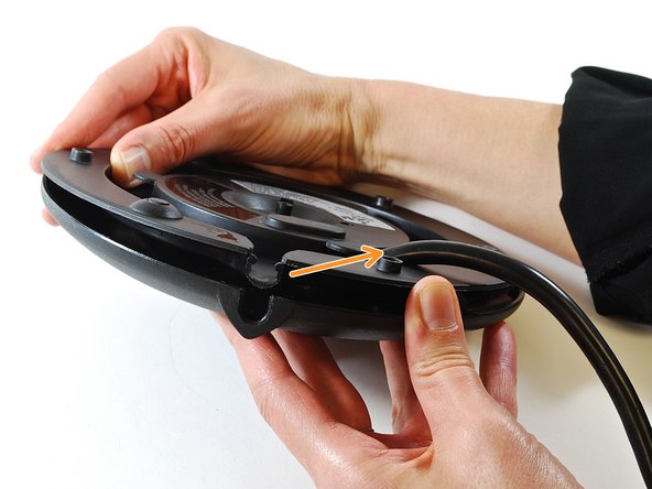
Align the two parts of the baseplate as shown in these two photos.
-
Push or pull on the cord as needed to ensure a stable fit before inserting the screws.
-
-
Dieser Schritt ist noch nicht übersetzt. Hilf mit, ihn zu übersetzen!
-
Align the holes on the two halves of the baseplate precisely.
-
Using a #1 Phillips head screwdriver, tighten the three 3/8" Philips head screws in the holes located along the outer edge of the base plate.
-
Using a #1 TRIANGULAR head screwdriver, tighten the 3/8" TRIANGULAR Phillips screw at the center of the base plate.
-
-
Dieser Schritt ist noch nicht übersetzt. Hilf mit, ihn zu übersetzen!
-
Your baseplate with the new cord attached should look similar to the one shown in the photo.
-


Rückgängig: Ich habe diese Anleitung nicht absolviert.
2 weitere Nutzer:innen haben diese Anleitung absolviert.
Team

New Mexico State, Team 1-1, Sheppard Spring 2014 Mitglied von New Mexico State, Team 1-1, Sheppard Spring 2014
NMSU-SHEPPARD-S14S1G1
4 Mitglieder
3 Anleitungen geschrieben