Zum Hauptinhalt wechseln

Chromo Inc. T2 Motherboard Replacement

Was du brauchst

  1. Chromo Inc. T2 Motherboard Replacement, Removing the Casing: Schritt 1, Bild 1 von 3 Chromo Inc. T2 Motherboard Replacement, Removing the Casing: Schritt 1, Bild 2 von 3 Chromo Inc. T2 Motherboard Replacement, Removing the Casing: Schritt 1, Bild 3 von 3
    • Place your Plastic Opening Tool between the screen and the case. Slowly move it around the casing while prying in a downward motion to undo the hinges holding the two together and separate the two parts.

  2. Chromo Inc. T2 Motherboard Replacement, Turn it around: Schritt 2, Bild 1 von 1
    • After separating the case and screen, turn your screen face down so you can see the internal parts!

  3. Chromo Inc. T2 Motherboard Replacement, Disconnecting Flex Cables: Schritt 3, Bild 1 von 2 Chromo Inc. T2 Motherboard Replacement, Disconnecting Flex Cables: Schritt 3, Bild 2 von 2
    • Peel back the tape holding the big flex cable in place.

    • Using your plastic opening tool, gently push back the gray connector to free the flex cables and then pull them out.

  4. Chromo Inc. T2 Motherboard Replacement, Disconnecting the Camera: Schritt 4, Bild 1 von 2 Chromo Inc. T2 Motherboard Replacement, Disconnecting the Camera: Schritt 4, Bild 2 von 2
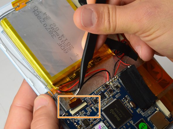
    • Using the small plastic opening tool, gently push the gray connector back to unlock the flex cable.

    • Using a pair of tweezers, gently grasp the flex cable and disconnect it from the connector.

  5. Chromo Inc. T2 Motherboard Replacement: Schritt 5, Bild 1 von 2 Chromo Inc. T2 Motherboard Replacement: Schritt 5, Bild 2 von 2
    • Using a Phillips #00 Precision Screwdriver, remove the three 3mm screws holding the motherboard.

  6. Chromo Inc. T2 Motherboard Replacement: Schritt 6, Bild 1 von 3 Chromo Inc. T2 Motherboard Replacement: Schritt 6, Bild 2 von 3 Chromo Inc. T2 Motherboard Replacement: Schritt 6, Bild 3 von 3
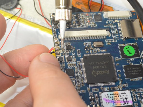
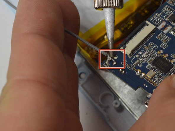
    • Using your soldering iron, desolder the six wires on the side of the logic board.

    • Note: Remember where these wires go as re-connecting them incorrectly can lead to damaging the device!

    • Soldering Iron gets very hot, take care to not touch anywhere on the soldering iron except for the handle!

  7. Chromo Inc. T2 Motherboard Replacement: Schritt 7, Bild 1 von 2 Chromo Inc. T2 Motherboard Replacement: Schritt 7, Bild 2 von 2
    • Using your soldering Iron, desolder the grounding cable on the motherboard.

    • Soldering Iron gets very hot, take care to not touch anywhere on the soldering iron except for the handle!

  8. Chromo Inc. T2 Motherboard Replacement: Schritt 8, Bild 1 von 1
    • Your motherboard is now ready for replacement!

Abschluss

To reassemble your device, follow these instructions in reverse order.

Team

USF Tampa, Team 15-1, Watkins Winter 2015 Mitglied von USF Tampa, Team 15-1, Watkins Winter 2015

USFT-WATKINS-W15S15G1

4 Mitglieder

6 Anleitungen geschrieben

0 Kommentare

Kommentar hinzufügen

Seitenaufrufe:

Letzte 24 Stunden: 0

Letzte 7 Tage: 0

Letzte 30 Tage: 1

Insgesamt: 633