Diese Version enthält möglicherweise inkorrekte Änderungen. Wechsle zur letzten geprüften Version.
Was du brauchst
-
Dieser Schritt ist noch nicht übersetzt. Hilf mit, ihn zu übersetzen!
-
Use a Phillips #00 screwdriver to unscrew the four 1.1mm long screws on each corner located at the top of the cover.
-
-
Dieser Schritt ist noch nicht übersetzt. Hilf mit, ihn zu übersetzen!
-
Similar to the last step, flip the cover over and use a Phillips #00 screwdriver to unscrew the four 1.1mm long screws on each corner located at the bottom of the cover.
-
Remove the warranty sticker across the bottom.
-
-
Dieser Schritt ist noch nicht übersetzt. Hilf mit, ihn zu übersetzen!
-
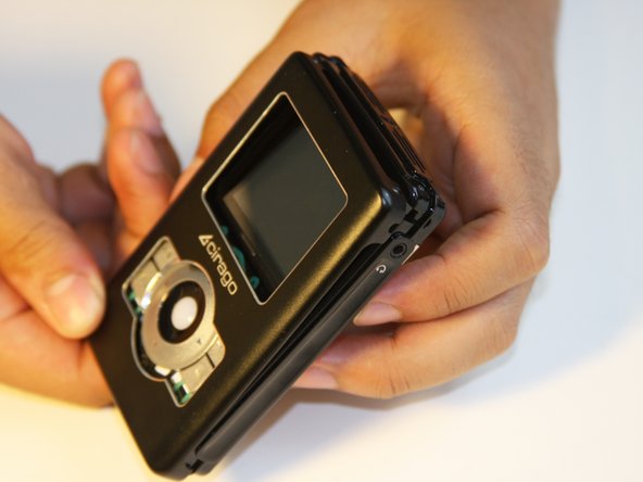
Gently take the cover apart using your hands separating the top and bottom.
-
The outer shell is expected to easily come apart.
-
-
Dieser Schritt ist noch nicht übersetzt. Hilf mit, ihn zu übersetzen!
-
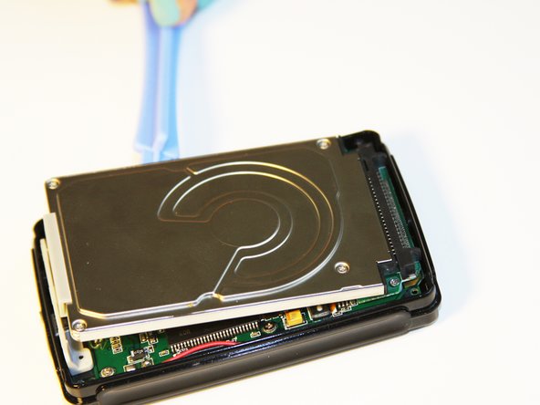
Make sure that the screen of the device is facing down.
-
-
Dieser Schritt ist noch nicht übersetzt. Hilf mit, ihn zu übersetzen!
-
Using the plastic opening tool, wedge the tool underneath the bottom left edge of the hard drive.
-
Raise the bottom edge of the hard drive 15 degrees up from the device.
-
-
Dieser Schritt ist noch nicht übersetzt. Hilf mit, ihn zu übersetzen!
-
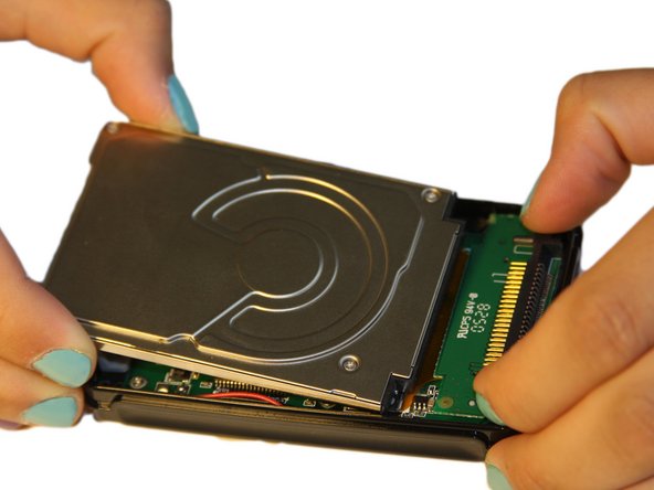
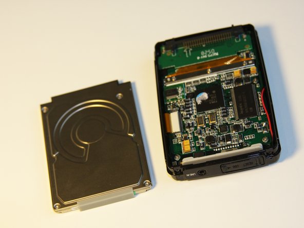
Place fingers on the IDE connectors gently picking up and sliding the hard drive out from the IDE module.
-
-
Dieser Schritt ist noch nicht übersetzt. Hilf mit, ihn zu übersetzen!
-
Using the Phillips #00 screwdriver, unscrew the two 1.5mm long screws holding the IDE connector to the motherboard located at the top.
-
-
Dieser Schritt ist noch nicht übersetzt. Hilf mit, ihn zu übersetzen!
-
Using the Phillips #00 screwdriver, unscrew the three 1.5mm long screws on the metal bracket.
-
-
Dieser Schritt ist noch nicht übersetzt. Hilf mit, ihn zu übersetzen!
-
Using the plastic opening tool, completely lift the metal bracket off of the motherboard.
-
Using the plastic opening tool, completely lift the rubber insulator off of the motherboard.
-
-
Dieser Schritt ist noch nicht übersetzt. Hilf mit, ihn zu übersetzen!
-
Using the plastic opening tool, completely lift the ribbon off of the motherboard.
-
-
Dieser Schritt ist noch nicht übersetzt. Hilf mit, ihn zu übersetzen!
-
Completely remove the IDE connector from the device.
-
The audio jack is attached to the IDE connector. Pull at a 45 degree angle from the audio jack.
-
-
Dieser Schritt ist noch nicht übersetzt. Hilf mit, ihn zu übersetzen!
-
Using the plastic opening tool, wedge the tool underneath the top edge of the motherboard.
-
Completely remove the motherboard.
-
-
Dieser Schritt ist noch nicht übersetzt. Hilf mit, ihn zu übersetzen!
-
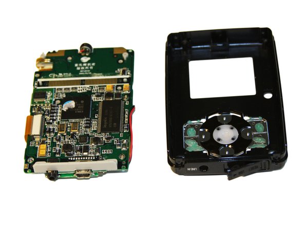
Set aside the front cover.
-
Flip over the motherboard.
-
Using the Philips #00 screwdriver, remove the three 4mm long screws holding down the button module.
-
-
Dieser Schritt ist noch nicht übersetzt. Hilf mit, ihn zu übersetzen!
-
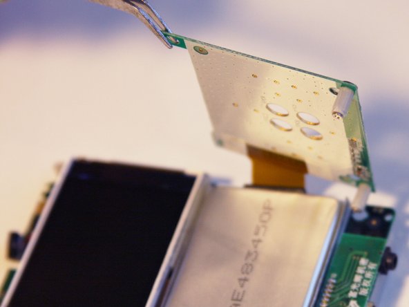
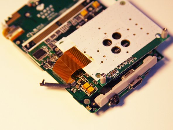
Using the tweezers, lift up the button module to a 180 degree angle.
-
Flip over the motherboard with the button module still attached.
-
-
Dieser Schritt ist noch nicht übersetzt. Hilf mit, ihn zu übersetzen!
-
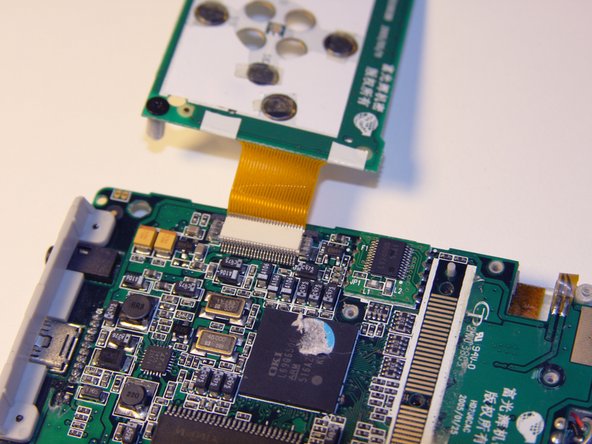
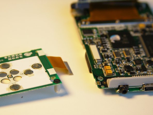
Fold the button module over the motherboard.
-
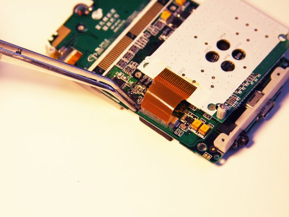
Using the tweezers, remove the ribbon pin.
-
-
Dieser Schritt ist noch nicht übersetzt. Hilf mit, ihn zu übersetzen!
-
The ribbon should easily detach from the motherboard.
-


Team

Cal Poly, Team 1-4, Regan SU 2012 Mitglied von Cal Poly, Team 1-4, Regan SU 2012
CPSU-REGAN-SU12S1G4
4 Mitglieder
7 Anleitungen geschrieben