Diese Version enthält möglicherweise inkorrekte Änderungen. Wechsle zur letzten geprüften Version.
Was du brauchst
-
Dieser Schritt ist noch nicht übersetzt. Hilf mit, ihn zu übersetzen!
-
Using a spudger, wedge the tip between the front and back case to pry them apart.
-
-
Dieser Schritt ist noch nicht übersetzt. Hilf mit, ihn zu übersetzen!
-
The black rubber button pad can be removed by simply picking it up.
-
-
Dieser Schritt ist noch nicht übersetzt. Hilf mit, ihn zu übersetzen!
-
Flip the LCD screen off the midsection plate to gain access to the space around the input button chip.
-
-
Dieser Schritt ist noch nicht übersetzt. Hilf mit, ihn zu übersetzen!
-
Using a spudger, pry off the button input chip from the mid-section of the device. To gain best leverage, start at the bottom right corner and level your way up the side of the chip.
-
-
-
Dieser Schritt ist noch nicht übersetzt. Hilf mit, ihn zu übersetzen!
-
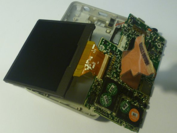
Lift open the LCD screen and button input chip to access the entire midsection plate.
-
-
Dieser Schritt ist noch nicht übersetzt. Hilf mit, ihn zu übersetzen!
-
Use a Phillips Head screwdriver to unscrew the three 3/16 inch screws that were underneath the button input chip.
-
-
Dieser Schritt ist noch nicht übersetzt. Hilf mit, ihn zu übersetzen!
-
Use a Phillips Head screwdriver to unscrew the three 3/16 inch screws that were underneath the LCD screen.
-
-
Dieser Schritt ist noch nicht übersetzt. Hilf mit, ihn zu übersetzen!
-
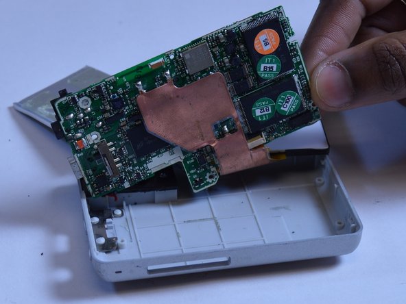
Lift the right edge of the motherboard off the back case.
-
Using two fingers to grip the edge of the board, slide the motherboard out of the case to the right.
-
-
Dieser Schritt ist noch nicht übersetzt. Hilf mit, ihn zu übersetzen!
-
Use two fingers to peel back the edge of the ribbon connector that is glued to the bottom of the LCD screen.
-
-
Dieser Schritt ist noch nicht übersetzt. Hilf mit, ihn zu übersetzen!
-
Using a plastic opening tool, unlock the ribbon connector by unlatching the black lever that pins it on the motherboard.
-
Once the black lever arm is open, pull the ribbon connector out to disconnect the LCD screen.
-


Rückgängig: Ich habe diese Anleitung nicht absolviert.
3 weitere Nutzer:innen haben diese Anleitung absolviert.
Team

USF Tampa, Team 1-1, Remmell Fall 2015 Mitglied von USF Tampa, Team 1-1, Remmell Fall 2015
USFT-REMMELL-F15S1G1
5 Mitglieder
14 Anleitungen geschrieben