Diese Version enthält möglicherweise inkorrekte Änderungen. Wechsle zur letzten geprüften Version.
Was du brauchst
-
Dieser Schritt ist noch nicht übersetzt. Hilf mit, ihn zu übersetzen!
-
Press down on battery door release tab to flip the battery door open.
-
-
Dieser Schritt ist noch nicht übersetzt. Hilf mit, ihn zu übersetzen!
-
Pull the two halves of the XT60 power connector apart.
-
-
Dieser Schritt ist noch nicht übersetzt. Hilf mit, ihn zu übersetzen!
-
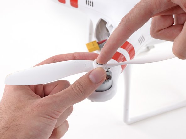
Silver-topped propeller collets unscrew counter-clockwise
-
Black-topped propeller collets unscrew clockwise
-
-
Dieser Schritt ist noch nicht übersetzt. Hilf mit, ihn zu übersetzen!
-
For propellors with silver collets: Use a 12 mm wrench or socket to loosen silver collets in the counter-clockwise direction.
-
Once free, unscrew and remove the collet.
-
-
-
Dieser Schritt ist noch nicht übersetzt. Hilf mit, ihn zu übersetzen!
-
For propellors with black collets: Use a 12 mm wrench or socket to loosen black collets in the clockwise direction.
-
Once free, unscrew and remove the collet.
-
-
Dieser Schritt ist noch nicht übersetzt. Hilf mit, ihn zu übersetzen!
-
Gently press down the motor shaft and lift the propeller up to remove it.
-
-
Dieser Schritt ist noch nicht übersetzt. Hilf mit, ihn zu übersetzen!
-
Remove the following screws from the underside of the drone:
-
Twelve 2.0 mm hex screws
-
Four Phillips #0 screws
-
-
Dieser Schritt ist noch nicht übersetzt. Hilf mit, ihn zu übersetzen!
-
Loosen the cable from the plastic landing gear.
-
Unplug the magnetometer molex connector.
-
-
Dieser Schritt ist noch nicht übersetzt. Hilf mit, ihn zu übersetzen!
-
Lift up on the top portion of the shell and set it on its side.
-
-
Dieser Schritt ist noch nicht übersetzt. Hilf mit, ihn zu übersetzen!
-
Lift the GPS cable molex connector up out of its socket on the main board.
-
-
Dieser Schritt ist noch nicht übersetzt. Hilf mit, ihn zu übersetzen!
-
Gently pull the slack of the magnetometer cable through the case bottom shell.
-
The case top shell should now have enough slack to work on the interior of the Phantom.
-
-
Dieser Schritt ist noch nicht übersetzt. Hilf mit, ihn zu übersetzen!
-
Twist the magnetometer cable as shown to prepare for passing it through the case bottom shell.
-
-
Dieser Schritt ist noch nicht übersetzt. Hilf mit, ihn zu übersetzen!
-
Gently push the twisted magnetometer cable and molex connector through the hole in the case bottom shell.
-
-
Dieser Schritt ist noch nicht übersetzt. Hilf mit, ihn zu übersetzen!
-
Remove the case top shell from the bottom shell.
-
If your new case top shell did not come with a GPS module, you may need to transfer the old one. To do so, gently peel off the large, gray adhesive label and transfer it to the new shell.
-


Rückgängig: Ich habe diese Anleitung nicht absolviert.
5 weitere Nutzer:innen haben diese Anleitung absolviert.

Team

Cal Poly, Team 25-89, Amido Spring 2010 Mitglied von Cal Poly, Team 25-89, Amido Spring 2010
CPSU-AMIDO-S10S25G89
4 Mitglieder
63 Anleitungen geschrieben
Ein Kommentar
Thanks for all the steps which are very helpful. Could you please let us know what toos is needed to remove the GPS module from the top shell?