Diese Version enthält möglicherweise inkorrekte Änderungen. Wechsle zur letzten geprüften Version.
Was du brauchst
-
Dieser Schritt ist noch nicht übersetzt. Hilf mit, ihn zu übersetzen!
-
In total, there are 12 exposed screws to remove from the back plate. Those 4 near the hinge (green) are captured screws and will remain with the backplate. 2 shorter screws (purple) retain the optical drive and must be removed prior to the drive. The remaining 7 (black) are standard screws.
-
Note: Retain screws within a lidded or magnetitic container during replacement to prevent accidental loss.
-
-
Dieser Schritt ist noch nicht übersetzt. Hilf mit, ihn zu übersetzen!
-
With both screws marked in purple removed, now slide out the disk drive, as marked with the arrow, to reveal the remaining, hidden pair of screws holding the backplate on.
-
-
-
Dieser Schritt ist noch nicht übersetzt. Hilf mit, ihn zu übersetzen!
-
Underneath the optical drive are two final screws preventing removal of the backplate. Remove both of the screws marked in red.
-
-
Dieser Schritt ist noch nicht übersetzt. Hilf mit, ihn zu übersetzen!
-
With all screws, the optical drive, and the pair of screws beneath it removed the backplate may now be gently pried apart from the main case with the use of plastic spudger. Work your tool about the entirety of the case and take care to never pry too hard on any single segment. If stuck near the hinge, ensure the capture screws are fully unscrewed.
-
Once removed, the internals will appear as pictured. Marked in red is the CPU fan we will be replacing.
-
-
Dieser Schritt ist noch nicht übersetzt. Hilf mit, ihn zu übersetzen!
-
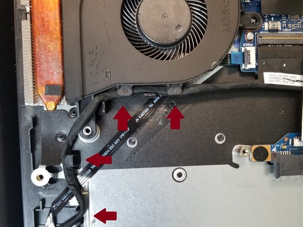
Remove the 3 screws marked in red before careful removal of the black cable marked with red arrows along the edge of the fan. During re-assembly, remember to re-thread the cable through its hooks as to preventing it getting in the way of the fan or optical drive.
-
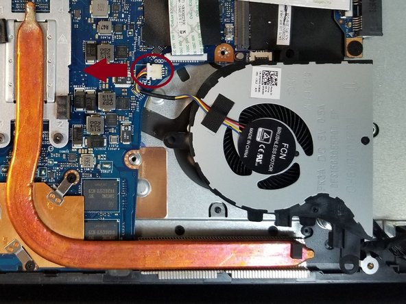
Use a plastic spudger to assist in disconnecting fan's power cable by pushing it in the direction marked by the red arrow. Take care to only apply pressure on the connector itself as to prevent damage to any other component on the motherboard. Light tugging on the cable itself once loosened can help.
-