Diese Version enthält möglicherweise inkorrekte Änderungen. Wechsle zur letzten geprüften Version.
Was du brauchst
-
Dieser Schritt ist noch nicht übersetzt. Hilf mit, ihn zu übersetzen!
-
Start by placing the laptop upside down to expose the first set of screws on the bottom of the laptop. Use your J1 Phillips head screwdriver bit to unscrew the 8 size 60 mm screws.
-
Remove the plastic cover to unveil the final screw holding the front and back frame together.
-
Remove this last screw of size 60mm with the J1 phillips head bit found in the approved iFixit toolkit.
-
-
Dieser Schritt ist noch nicht übersetzt. Hilf mit, ihn zu übersetzen!
-
Open the latches and disconnect the touch-pad cable and keyboard cable from the system board.
-
-
Dieser Schritt ist noch nicht übersetzt. Hilf mit, ihn zu übersetzen!
-
Disconnect the battery cable from the system board.
-
Remove the screws that secure the battery to the palm rest and keyboard assembly by using the PH1 screw driver to unscrew the three size 40 mm battery screws.
-
-
Dieser Schritt ist noch nicht übersetzt. Hilf mit, ihn zu übersetzen!
-
Open the latch and disconnect the I/O-board cable from system board.
-
-
-
Dieser Schritt ist noch nicht übersetzt. Hilf mit, ihn zu übersetzen!
-
Remove the 2mm screw that secures the motherboard and keyboard assembly.
-
-
Dieser Schritt ist noch nicht übersetzt. Hilf mit, ihn zu übersetzen!
-
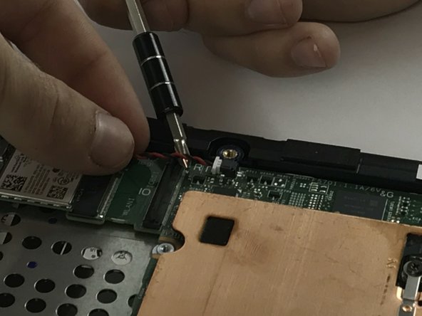
Disconnect the coin-cell battery cable from the system board.
-
-
Dieser Schritt ist noch nicht übersetzt. Hilf mit, ihn zu übersetzen!
-
Removing the Wireless WLAN Card
-
Remove the M2 x 3mm bracket screw.
-
Remove the metal bracket.
-
With tweezers, detach the white and black antenna cables connected to the Wireless WLAN Card.
-
Remove the Wireless WLAN Card by slide the assembly out of motherboard wireless socket.
-
-
Dieser Schritt ist noch nicht übersetzt. Hilf mit, ihn zu übersetzen!
-
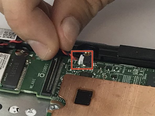
Disconnect the speaker cable from the system board.
-
-
Dieser Schritt ist noch nicht übersetzt. Hilf mit, ihn zu übersetzen!
-
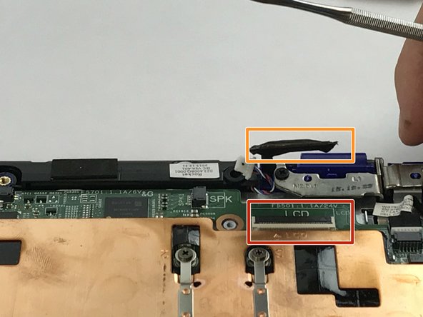
Remove the M2xL3 screw on display-cable guard to the system board.
-
Detach the cable beneath.
-
-
Dieser Schritt ist noch nicht übersetzt. Hilf mit, ihn zu übersetzen!
-
Disconnect the power-adapter port cable from the system board.
-
-
Dieser Schritt ist noch nicht übersetzt. Hilf mit, ihn zu übersetzen!
-
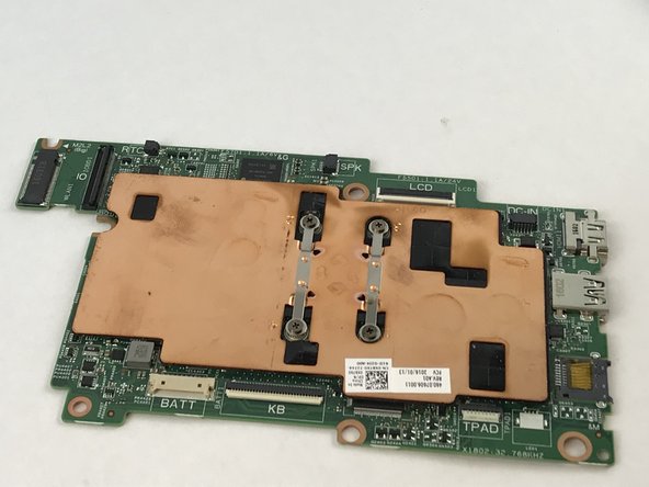
Lift the mother board off the palm rest and keyboard assembly.
-


Rückgängig: Ich habe diese Anleitung nicht absolviert.
Ein:e weitere:r Nutzer:in hat diese Anleitung absolviert.
Team

USF Tampa, Team S6-G4, Eyestone Spring 2018 Mitglied von USF Tampa, Team S6-G4, Eyestone Spring 2018
USFT-EYESTONE-S18S6G4
4 Mitglieder
6 Anleitungen geschrieben