Diese Version enthält möglicherweise inkorrekte Änderungen. Wechsle zur letzten geprüften Version.
Was du brauchst
-
-
Auf der Unterseite des Laptops befindet sich ein Schalter zum Entriegeln des Akkus.
-
-
-
Schiebe den Schalter zum Entriegeln des Akkus vom Schloßsymbol weg, bis der Akku hörbar klickt.
-
Schiebe den Akku zur Rückseite des Laptops, bis er sich löst.
-
-
Dieser Schritt ist noch nicht übersetzt. Hilf mit, ihn zu übersetzen!
-
Remove the two 4.00 mm Phillips #1 screws from the battery tray.
-
-
Dieser Schritt ist noch nicht übersetzt. Hilf mit, ihn zu übersetzen!
-
Insert the flat end of a spudger into the slot on the right side of the central control cover and pry it up.
-
Carefully pull the central control cover up along its edges.
-
-
Dieser Schritt ist noch nicht übersetzt. Hilf mit, ihn zu übersetzen!
-
Peel back the silver tape securing the ribbon cable to the cover.
-
Pull the small brown latch on the ribbon cable connector out.
-
Disconnect the ribbon cable to completely free the central control cover.
-
-
-
Dieser Schritt ist noch nicht übersetzt. Hilf mit, ihn zu übersetzen!
-
Remove the two 5.75 mm Phillips #1 screws securing the keyboard to the laptop.
-
Gently slide the keyboard towards the display until the tabs on its front side are free.
-
-
Dieser Schritt ist noch nicht übersetzt. Hilf mit, ihn zu übersetzen!
-
Use a spudger to gently lift the ribbon cable retaining flap.
-
Disconnect the ribbon cable.
-
Shift the keyboard sideways enough to free one side from it's retaining tab. Then lift the keyboard away from the laptop.
-
-
Dieser Schritt ist noch nicht übersetzt. Hilf mit, ihn zu übersetzen!
-
Remove/loosen the eight 4.80 mm Phillips #1 screws securing the bottom panel.
-
The screws may only need to be loosened, as they are generally retained by plastic washers.
-
Remove the bottom panel.
-
-
Dieser Schritt ist noch nicht übersetzt. Hilf mit, ihn zu übersetzen!
-
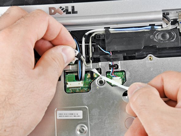
Disconnect the five antennas from their respective cards.
-
De-route the antennas from their routing retainers.
-
-
Dieser Schritt ist noch nicht übersetzt. Hilf mit, ihn zu übersetzen!
-
Remove the two 5.70 mm Phillips #1 screws securing the display assembly to the bottom case half.
-
-
Dieser Schritt ist noch nicht übersetzt. Hilf mit, ihn zu übersetzen!
-
Use the flat end of a spudger to push the camera connector out of its socket. Alternate pushing on either side to evenly remove the connector.
-
Carefully release the connector from its retaining tabs.
-
-
Dieser Schritt ist noch nicht übersetzt. Hilf mit, ihn zu übersetzen!
-
Push the antenna wires up through their hole in the bottom case half.
-
Release the antennas from their retaining tabs on the upper case.
-
-
Dieser Schritt ist noch nicht übersetzt. Hilf mit, ihn zu übersetzen!
-
Disconnect the flat LCD ribbon cable by pulling it up by the tab.
-
Free the ribbon cable from its retaining clips.
-
-
Dieser Schritt ist noch nicht übersetzt. Hilf mit, ihn zu übersetzen!
-
Remove the four 3.45 mm Phillips #1 screws securing the display assembly to the laptop chassis.
-
Remove the display assembly from the laptop.
-


Rückgängig: Ich habe diese Anleitung nicht absolviert.
8 weitere Nutzer:innen haben diese Anleitung absolviert.

Ein Kommentar
Hi There,
Thanks for the great article. Can you please advise what is the part number (LCD number). For example I have LTN156AT17-101 for my Inspiron N5110. I am actually planning to use the screen from 1525 to replace the one in N5110. Are they both same connector type? Thanks.