Diese Version enthält möglicherweise inkorrekte Änderungen. Wechsle zur letzten geprüften Version.
Was du brauchst
-
Dieser Schritt ist noch nicht übersetzt. Hilf mit, ihn zu übersetzen!
-
Slide the highlighted tab to the left.
-
With your finger on the tab, remove the battery by lifting it upwards away from the laptop.
-
-
Dieser Schritt ist noch nicht übersetzt. Hilf mit, ihn zu übersetzen!
-
Remove the six 16.7mm screws inside the circled holes.
-
-
Dieser Schritt ist noch nicht übersetzt. Hilf mit, ihn zu übersetzen!
-
Rotate the ThinkPad so that the hard drive bay is facing you.
-
Remove the black cover to reveal a 14.8mm screw.
-
Remove the uncovered screw with a Phillips #0 screwdriver.
-
-
Dieser Schritt ist noch nicht übersetzt. Hilf mit, ihn zu übersetzen!
-
Pry apart the keyboard with a plastic opening tool or with your fingers.
-
-
Dieser Schritt ist noch nicht übersetzt. Hilf mit, ihn zu übersetzen!
-
Lift the front end of the keyboard as shown.
-
Using your fingers, remove the black film cover.
-
-
Dieser Schritt ist noch nicht übersetzt. Hilf mit, ihn zu übersetzen!
-
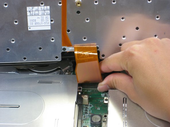
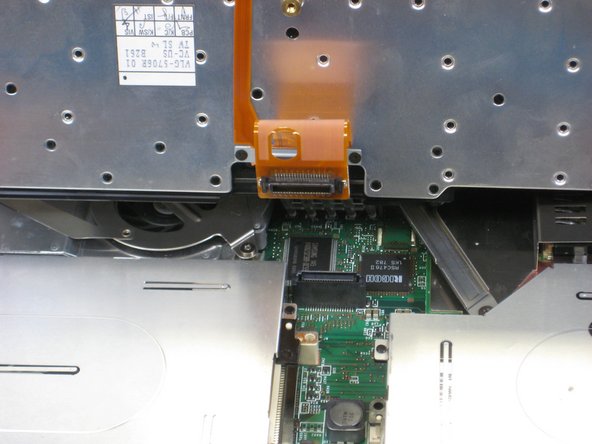
Locate the connector attached to the motherboard.
-
Disconnect the ribbon cable by removing the connector.
-
-
Dieser Schritt ist noch nicht übersetzt. Hilf mit, ihn zu übersetzen!
-
Lift and remove the keyboard.
-
Remove the two 5.6mm screws.
-
Remove the 16.7mm screw.
-
-
Dieser Schritt ist noch nicht übersetzt. Hilf mit, ihn zu übersetzen!
-
Pry off the upper case with your hands.
-
-
Dieser Schritt ist noch nicht übersetzt. Hilf mit, ihn zu übersetzen!
-
Remove the 5.6mm screw that holds the LCD to the upper case.
-
-
Dieser Schritt ist noch nicht übersetzt. Hilf mit, ihn zu übersetzen!
-
Remove the 5.6mm screw on the left side of the three-pronged connector.
-
Remove the other two 16.7mm screws.
-
Lift and remove connector.
-
-
-
Dieser Schritt ist noch nicht übersetzt. Hilf mit, ihn zu übersetzen!
-
Pull out the white tab connecting the LCD to the motherboard.
-
-
Dieser Schritt ist noch nicht übersetzt. Hilf mit, ihn zu übersetzen!
-
Turn the laptop so that the back is facing you.
-
Remove the four 5.6mm long screws.
-
-
Dieser Schritt ist noch nicht übersetzt. Hilf mit, ihn zu übersetzen!
-
Gently lift the LCD monitor up and out.
-
Remove the black plastic tab.
-
-
Dieser Schritt ist noch nicht übersetzt. Hilf mit, ihn zu übersetzen!
-
Remove the following screws from the fan retention bracket:
-
Single 5.6 mm screw.
-
Three 16.1 mm screws.
-
-
Dieser Schritt ist noch nicht übersetzt. Hilf mit, ihn zu übersetzen!
-
Lift the fan/heatsink assembly up.
-
Locate the fan power cable and pull upwards near the connector.
-
Remove the fan/heatsink assembly.
-
-
Dieser Schritt ist noch nicht übersetzt. Hilf mit, ihn zu übersetzen!
-
Locate the floppy drive bay.
-
Remove the four 5.6mm screws.
-
Remove the 16mm screw.
-
-
Dieser Schritt ist noch nicht übersetzt. Hilf mit, ihn zu übersetzen!
-
Turn the laptop over so the battery is facing you.
-
Locate the modem and ethernet card bay.
-
Remove the two 5.3mm cover screws.
-
Gently lift the cover.
-
-
Dieser Schritt ist noch nicht übersetzt. Hilf mit, ihn zu übersetzen!
-
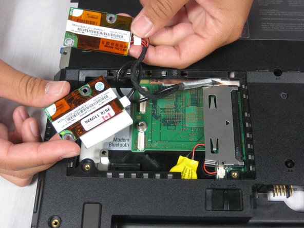
Remove the four 9.1mm screws attached to the modem and ethernet cards.
-
Gently lift the modem and ethernet cards.
-
-
Dieser Schritt ist noch nicht übersetzt. Hilf mit, ihn zu übersetzen!
-
Locate the hard drive slot.
-
Remove the 8.8mm screw with a Phillips #0 screwdriver.
-
-
Dieser Schritt ist noch nicht übersetzt. Hilf mit, ihn zu übersetzen!
-
Turn the laptop over again and orient it as shown.
-
Lift the left side of the floppy disk bay and and pull it out.
-
-
Dieser Schritt ist noch nicht übersetzt. Hilf mit, ihn zu übersetzen!
-
Locate the CD Drive Bay
-
Remove the three 5.6mm screws.
-
Remove the 16mm screw.
-
Lift the right side and pull the CD drive bay out.
-
-
Dieser Schritt ist noch nicht übersetzt. Hilf mit, ihn zu übersetzen!
-
Locate the speakers on the bottom left and right of the ThinkPad A30.
-
-
Dieser Schritt ist noch nicht übersetzt. Hilf mit, ihn zu übersetzen!
-
Remove the 5.6mm screws on each speaker.
-
Pull the right speaker out, making sure there is still slack in the wire.
-
-
Dieser Schritt ist noch nicht übersetzt. Hilf mit, ihn zu übersetzen!
-
Pull the blue tab that holds the speaker chip and pull the chip out.
-
-
Dieser Schritt ist noch nicht übersetzt. Hilf mit, ihn zu übersetzen!
-
Remove the wires from the white tabs by lifting the black wire casing.
-
-
Dieser Schritt ist noch nicht übersetzt. Hilf mit, ihn zu übersetzen!
-
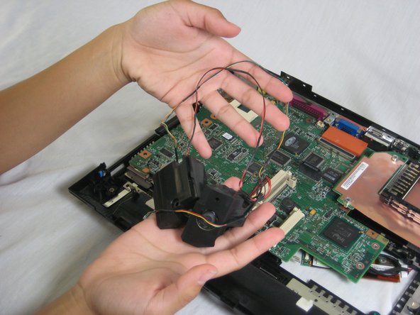
Lift the left speaker out.
-
Pull the blue tab that holds the speaker chip and pull the chip out.
-
-
Dieser Schritt ist noch nicht übersetzt. Hilf mit, ihn zu übersetzen!
-
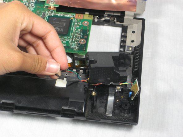
Remove the speaker data and power cables by pulling them from the motherboard.
-
You have successfully removed the ThinkPad A30 speakers.
-


Rückgängig: Ich habe diese Anleitung nicht absolviert.
Ein:e weitere:r Nutzer:in hat diese Anleitung absolviert.

Team

Cal Poly, Team 4-44, Amido Fall 2010 Mitglied von Cal Poly, Team 4-44, Amido Fall 2010
CPSU-AMIDO-F10S4G44
4 Mitglieder
26 Anleitungen geschrieben