Diese Version enthält möglicherweise inkorrekte Änderungen. Wechsle zur letzten geprüften Version.
Was du brauchst
-
Dieser Schritt ist noch nicht übersetzt. Hilf mit, ihn zu übersetzen!
-
Turning over your phone, place two fingers on the back cover and apply pressure away from the camera to slide the back cover off.
-
-
Dieser Schritt ist noch nicht übersetzt. Hilf mit, ihn zu übersetzen!
-
Pinch the battery pull tab located below the camera, pull it upwards, and remove the battery.
-
-
Dieser Schritt ist noch nicht übersetzt. Hilf mit, ihn zu übersetzen!
-
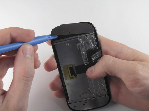
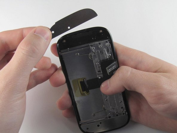
Wedge a plastic opening tool behind the panel covering the camera, pry it up, and remove it using your fingers.
-
-
Dieser Schritt ist noch nicht übersetzt. Hilf mit, ihn zu übersetzen!
-
Remove the six 4.0 mm T4 Torx screws which line the edge of the back of the phone.
-
-
Dieser Schritt ist noch nicht übersetzt. Hilf mit, ihn zu übersetzen!
-
Turn the phone over and slide out the keyboard.
-
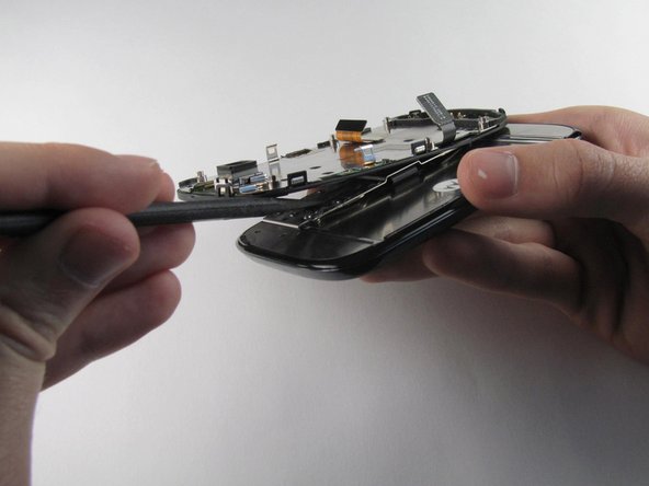
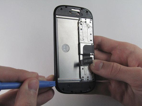
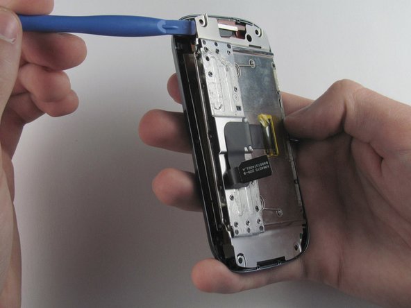
Wedge a plastic opening tool where the keyboard meets the back casing of the phone next to the headphone jack.
-
Carefully pry open the back casing along the keyboard's edge until at least two corners of the back casing are separated from the keyboard.
-
-
Dieser Schritt ist noch nicht übersetzt. Hilf mit, ihn zu übersetzen!
-
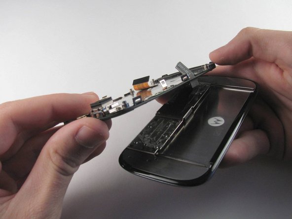
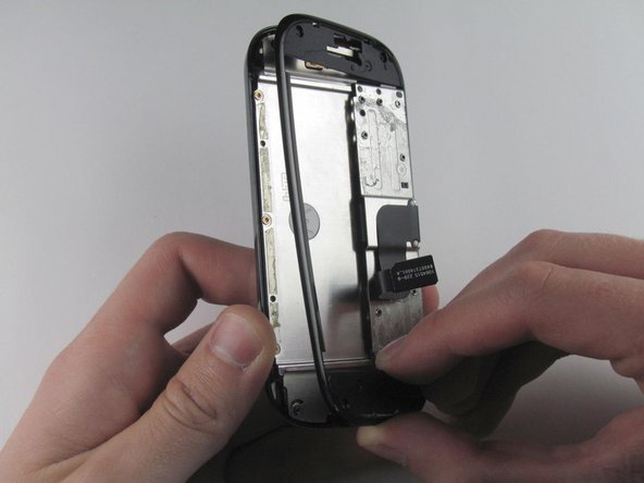
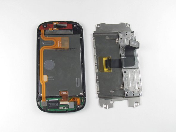
Carefully separate the back casing from the rest of the phone.
-
-
Dieser Schritt ist noch nicht übersetzt. Hilf mit, ihn zu übersetzen!
-
Gently pry ZIF connector upwards using the flat end of a spudger tool.
-
-
-
Dieser Schritt ist noch nicht übersetzt. Hilf mit, ihn zu übersetzen!
-
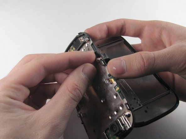
Press your thumb against the orange power cable and pull it down slowly to disconnect the power cable from the bottom of the keyboard.
-
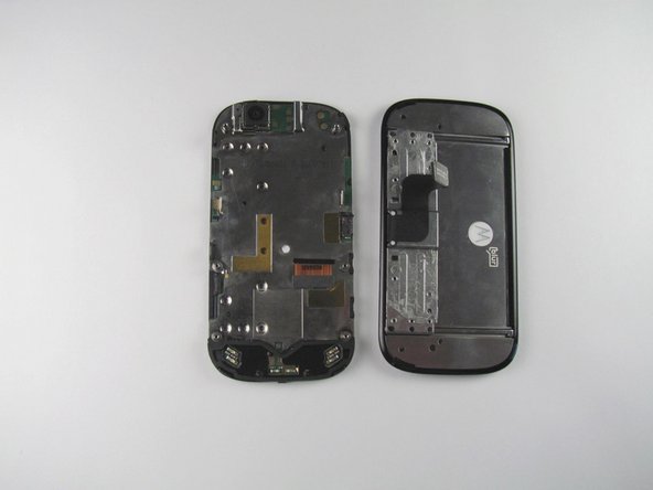
The rear casing and the rest of the phone should now be completely separated.
-
-
Dieser Schritt ist noch nicht übersetzt. Hilf mit, ihn zu übersetzen!
-
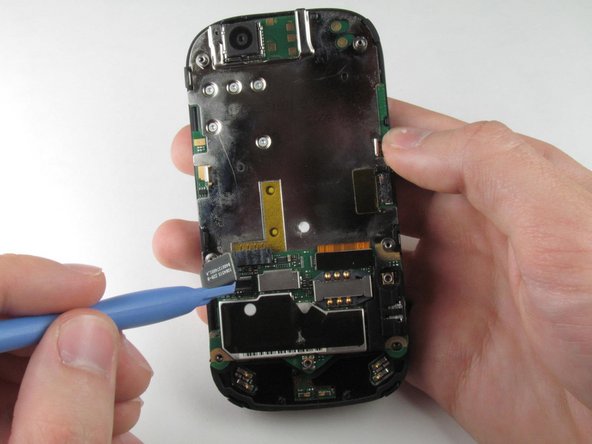
Wedge the plastic opening tool underneath the black display connector and pry it off its socket on the motherboard.
-
-
Dieser Schritt ist noch nicht übersetzt. Hilf mit, ihn zu übersetzen!
-
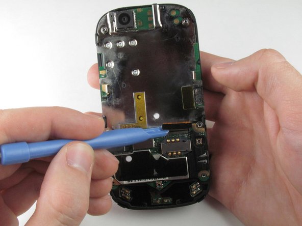
Pry the orange keyboard connector from its socket on the motherboard using the edge of the plastic opening tool.
-
-
Dieser Schritt ist noch nicht übersetzt. Hilf mit, ihn zu übersetzen!
-
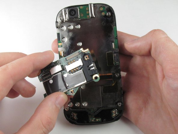
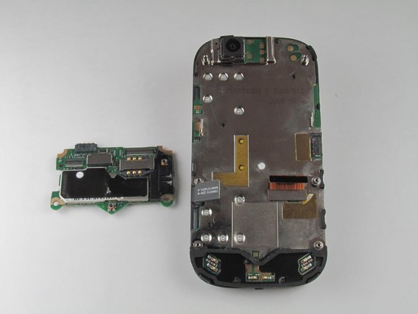
Carefully grab the sides of the motherboard with your fingers and remove it from the phone.
-
-
Dieser Schritt ist noch nicht übersetzt. Hilf mit, ihn zu übersetzen!
-
Remove the ten 3.0 mm T4 Torx screws near the black display cable.
-
-
Dieser Schritt ist noch nicht übersetzt. Hilf mit, ihn zu übersetzen!
-
Orient the phone so that the edge closest to the camera points towards you and slide out the keyboard.
-
Wedge the tip of a spudger between the keyboard and the display assembly below the camera.
-
With steady pressure, pry the keyboard away from the display assembly.
-
-
Dieser Schritt ist noch nicht übersetzt. Hilf mit, ihn zu übersetzen!
-
Grab the display flex cable and gently push it through the notch it is coming out of.
-
-
Dieser Schritt ist noch nicht übersetzt. Hilf mit, ihn zu übersetzen!
-
Wedge a plastic opening tool underneath one of the metal panels on the underside of the display assembly.
-
Pry upwards and remove the metal panel.
-
Repeat this step for the second metal panel located on the opposite side of the phone.
-
-
Dieser Schritt ist noch nicht übersetzt. Hilf mit, ihn zu übersetzen!
-
Remove the four 3.0 mm T4 Torx screws at the corners of the phone.
-
-
Dieser Schritt ist noch nicht übersetzt. Hilf mit, ihn zu übersetzen!
-
Wedge a plastic opening tool between the edge and the black pastic cover on the underside of the display assembly.
-
Run the plastic opening tool along the edges to separate the black plastic cover from the display assembly.
-
Remove the black plastic cover.
-
-
Dieser Schritt ist noch nicht übersetzt. Hilf mit, ihn zu übersetzen!
-
Remove the six 3.0 mm T4 Torx screws that align on the phone's sides.
-
-
Dieser Schritt ist noch nicht übersetzt. Hilf mit, ihn zu übersetzen!
-
Insert a plastic opening tool between the LCD shield plate and a corner of the keyboard slider plate.
-
Pry apart the keyboard slider plate and LCD shield plate.
-
-
Dieser Schritt ist noch nicht übersetzt. Hilf mit, ihn zu übersetzen!
-
Pry the display flex cable from its connector on the LCD shield plate with a plastic opening tool.
-
Separate the display flex cable from the LCD cover plate.
-


Rückgängig: Ich habe diese Anleitung nicht absolviert.
Ein:e weitere:r Nutzer:in hat diese Anleitung absolviert.

Team

Cal Poly, Team 10-42, Amido Spring 2013 Mitglied von Cal Poly, Team 10-42, Amido Spring 2013
CPSU-AMIDO-S13S10G42
4 Mitglieder
16 Anleitungen geschrieben