Diese Version enthält möglicherweise inkorrekte Änderungen. Wechsle zur letzten geprüften Version.
Was du brauchst
-
Dieser Schritt ist noch nicht übersetzt. Hilf mit, ihn zu übersetzen!
-
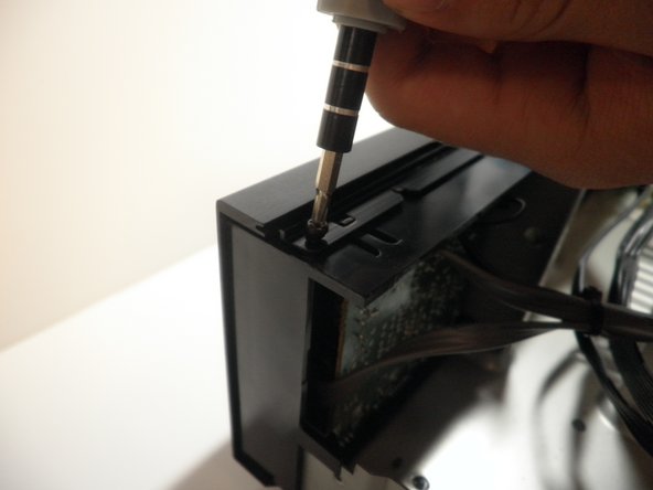
Remove the two screws on both sides of the receiver. Keep these and the rest of the screws in a safe place.
-
-
Dieser Schritt ist noch nicht übersetzt. Hilf mit, ihn zu übersetzen!
-
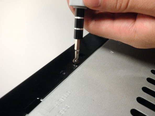
Remove the top screw on the back panel.
-
-
Dieser Schritt ist noch nicht übersetzt. Hilf mit, ihn zu übersetzen!
-
Slide off the case to expose the internal components of the receiver.
-
-
-
Dieser Schritt ist noch nicht übersetzt. Hilf mit, ihn zu übersetzen!
-
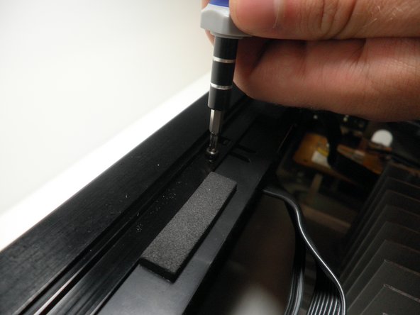
Unscrew the three screws on top of the face plate.
-
-
Dieser Schritt ist noch nicht übersetzt. Hilf mit, ihn zu übersetzen!
-
Unscrew the one screw on the bottom of the front panel.
-
-
Dieser Schritt ist noch nicht übersetzt. Hilf mit, ihn zu übersetzen!
-
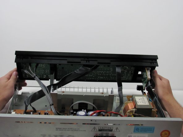
Simultaneously push down on the head of the snap on each end of the device with your thumbs and push to seperate the face plate. This may take some force.
-
-
Dieser Schritt ist noch nicht übersetzt. Hilf mit, ihn zu übersetzen!
-
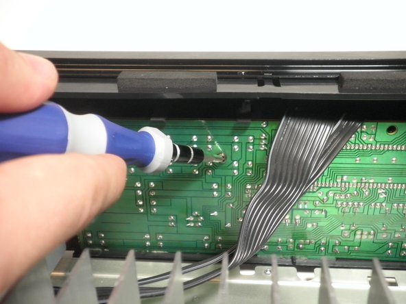
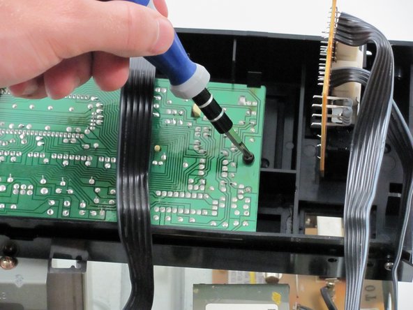
On the inside middle of the face plate you will see two screws in the logic board. Unscrew these two screws.
-
-
Dieser Schritt ist noch nicht übersetzt. Hilf mit, ihn zu übersetzen!
-
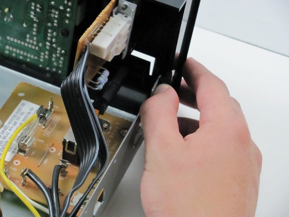
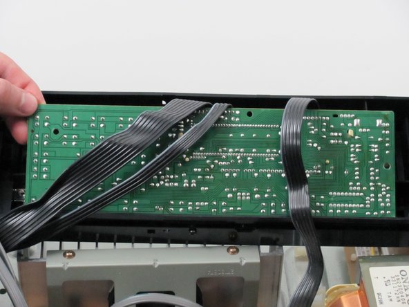
You will see the same snaps along the top of the logic board. Press the heads of the snaps down and pull the logic board out and up.
-


Rückgängig: Ich habe diese Anleitung nicht absolviert.
Ein:e weitere:r Nutzer:in hat diese Anleitung absolviert.
Team

Cal Poly, Team 27-92, Amido Spring 2010 Mitglied von Cal Poly, Team 27-92, Amido Spring 2010
CPSU-AMIDO-S10S27G92
4 Mitglieder
7 Anleitungen geschrieben