Diese Version enthält möglicherweise inkorrekte Änderungen. Wechsle zur letzten geprüften Version.
Was du brauchst
-
Dieser Schritt ist noch nicht übersetzt. Hilf mit, ihn zu übersetzen!
-
Loosen the two screws on the battery panel. Then lift the panel up to remove it.
-
-
Dieser Schritt ist noch nicht übersetzt. Hilf mit, ihn zu übersetzen!
-
L Button.
-
Top of the battery pack.
-
To remove the battery pack, place your fingernail or a spudger at the top of the battery near the L button. Gently lift the battery out.
-
-
-
Zwei Schrauben befinden sich unter den beiden Gummifüßen (rot markiert).
-
Benutze die Spitze eines Spudger, um die Gummifüße aus dem Gehäuse zu lösen.
-
-
-
Entferne die Schrauben, mit denen das untere Gehäuse am DSi befestigt ist:
-
Sechs 5,2 mm Kreuzschlitzschrauben #00
-
Eine 2,7 mm Kreuzschlitzschraube #00
-
-
-
-
Setze den Spudger nahe der oberen rechten Ecke des DSi zwischen dem unteren Gehäuseteil und dem Bildschirm ein.
-
Führe den Spudger vorsichtig an der Kante des Außengehäuses entlang, damit eine Öffnung zwischen dem Hauptteil und dem Gehäuse entsteht.
-
Führe den Spudger weiter um das Gehäuse des DSi herum, bis der größte Teil des unteren Gehäuses entfernt wurde.
-
-
-
Hebe das untere Gehäuse vorsichtig an der Unterkante an.
-
Löse das Kabel der Lautstärkeregelung und der SD-Karte mit einem Spudger aus dem Anschluss auf der Hauptplatine.
-
Sobald das Kabel vollständig entfernt ist, lässt sich das gesamte Außengehäuse abnehmen.
-
-
-
Ziehe das WLAN-Modul an der Kante, die sich am nächsten zur Kopfhörerbuchse befindet, von der Hauptplatine ab.
-
-
-
Entferne den WLAN-Antennenstecker gerade aus seinem Anschluss auf der WLAN-Platine.
-
-
Dieser Schritt ist noch nicht übersetzt. Hilf mit, ihn zu übersetzen!
-
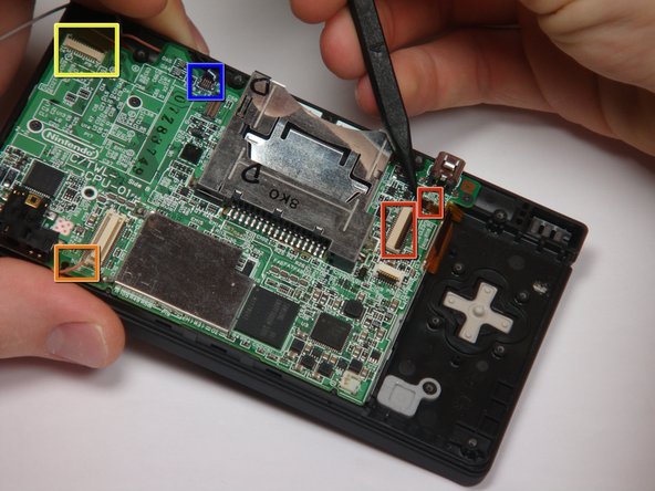
Flip up the black latch and disconnect the D-Pad/Power Button ribbon cable.
-
-
Dieser Schritt ist noch nicht übersetzt. Hilf mit, ihn zu übersetzen!
-
The connector is two pieces -- a white "male" piece (connected to the wires), and a beige "female" part (soldered to the main board).
-
There is a small "notch" in the female part, to give you a place to insert a small flat-head screwdriver. Put the corner of your screwdriver in there, and twist it gently to push the white part up (away from the main board). Do not try to pull it to the right (towards the battery board).
-
-
Dieser Schritt ist noch nicht übersetzt. Hilf mit, ihn zu übersetzen!
-
If you have not already done so, disconnect the two bottom-LCD ribbon cables from the main board by prying up the black latches and pulling the cable out to the side.
-
The ribbon cable (marked in blue) for the touch screen is particularly thin and fragile; be careful to avoid bending it more than necessary.
-
Flip up the latch and remove the touch screen cable.
-
Flip up the latch and remove the top-screen ribbon cable.
-
Pry up on the orange cable to disconnect it from the main board, much like the antenna cable on the Wi-Fi module.
-