Diese Version enthält möglicherweise inkorrekte Änderungen. Wechsle zur letzten geprüften Version.
Was du brauchst
-
Dieser Schritt ist noch nicht übersetzt. Hilf mit, ihn zu übersetzen!
-
Remove the four Phillips head screws that fasten the motor hub to the tube adapter.
-
-
Dieser Schritt ist noch nicht übersetzt. Hilf mit, ihn zu übersetzen!
-
Using a flathead screwdriver, pry the bearing cap from the tube.
-
-
-
Dieser Schritt ist noch nicht übersetzt. Hilf mit, ihn zu übersetzen!
-
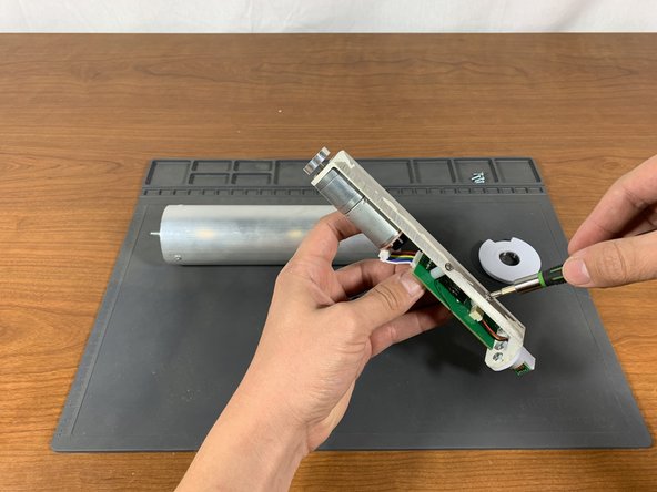
Use a #1 Phillips head screwdriver to loosen the PCB mounting screws until the circuit board can be adjusted. This should only take 1-2 full rotations of the screwdriver. Do not fully remove the screws.
-
-
Dieser Schritt ist noch nicht übersetzt. Hilf mit, ihn zu übersetzen!
-
The circuit board can cause problems if it is not properly centered on the sheet metal mount. See the picture for details.
-
The blue lines in the picture show the edges of the white metal PCB plate, while the red lines show the edge of the PCB. Adjust the PCB so it lines up as closely as possible with the metal plate. This will ensure that the PCB does not contact the edge of the tube while rotating.
-
-
Dieser Schritt ist noch nicht übersetzt. Hilf mit, ihn zu übersetzen!
-
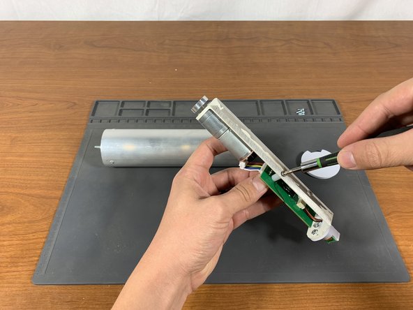
Tighten the two PCB mounting screws until the PCB cannot move freely.
-