Diese Version enthält möglicherweise inkorrekte Änderungen. Wechsle zur letzten geprüften Version.
Was du brauchst
-
Dieser Schritt ist noch nicht übersetzt. Hilf mit, ihn zu übersetzen!
-
Lift the top of the printer to see the inside.
-
-
Dieser Schritt ist noch nicht übersetzt. Hilf mit, ihn zu übersetzen!
-
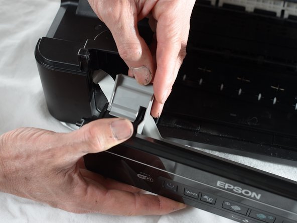
Locate the control panel, the part of the printer with the buttons on it.
-
Push the control panel away from the outside of the printer, taking the panel out of the holes that hold it in place.
-
Repeat the above step for the other side of the control panel.
-
-
Dieser Schritt ist noch nicht übersetzt. Hilf mit, ihn zu übersetzen!
-
The front control panel is attached to the printer on both sides by a grey piece of plastic that runs on a track. Remove the control panel from the track by pushing it away from the track on both sides.
-
-
-
Dieser Schritt ist noch nicht übersetzt. Hilf mit, ihn zu übersetzen!
-
Flip the detached control panel over so that the buttons are facing down.
-
Remove the two 3mm Phillips #2 screws from the back of the control panel.
-
-
Dieser Schritt ist noch nicht übersetzt. Hilf mit, ihn zu übersetzen!
-
Lift up the gray plastic piece.
-
Remove the 3mm Phillips #2 screw.
-
-
Dieser Schritt ist noch nicht übersetzt. Hilf mit, ihn zu übersetzen!
-
Split the control panel in half by gently pulling on both sides of the seam that runs through the control panel.
-
-
Dieser Schritt ist noch nicht übersetzt. Hilf mit, ihn zu übersetzen!
-
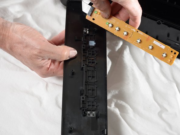
Separate the two pieces to reveal the green circuit board.
-
Remove the green circuit board by lifting it up gently with your hands.
-
-
Dieser Schritt ist noch nicht übersetzt. Hilf mit, ihn zu übersetzen!
-
Remove the buttons with the plastic opening tool by pressing the front panel down and lifting the buttons up.
-


Rückgängig: Ich habe diese Anleitung nicht absolviert.
2 weitere Nutzer:innen haben diese Anleitung absolviert.
Team

Cal Poly, Team 6-1, Forte Spring 2014 Mitglied von Cal Poly, Team 6-1, Forte Spring 2014
CPSU-FORTE-S14S6G1
4 Mitglieder
10 Anleitungen geschrieben