Diese Version enthält möglicherweise inkorrekte Änderungen. Wechsle zur letzten geprüften Version.
Was du brauchst
-
Dieser Schritt ist noch nicht übersetzt. Hilf mit, ihn zu übersetzen!
-
There are 4 black screws that need to be removed on the top of the lid. A 1.5mm flathead screwdriver will work on the star shaped screw heads.
-
-
-
Dieser Schritt ist noch nicht übersetzt. Hilf mit, ihn zu übersetzen!
-
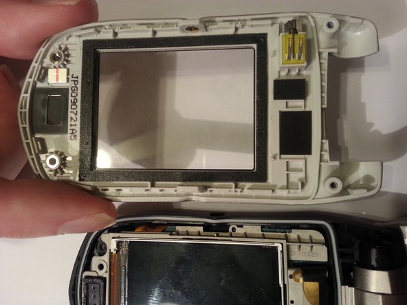
Use a plastic opening tool to remove the screen cover from the rest of the lid.
-
-
Dieser Schritt ist noch nicht übersetzt. Hilf mit, ihn zu übersetzen!
-
Your phone should look like the picture to the left.
-
-
Dieser Schritt ist noch nicht übersetzt. Hilf mit, ihn zu übersetzen!
-
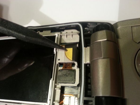
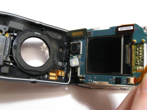
Remove one screw located on the left side of the phone with the pictured orientation in mind.
-
This will release the logic board from the back case.
-
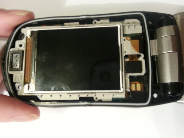
Lift the board out of the case starting with the top. Continue to fold it forwards to access the ribbon cable still connecting it.
-
-
Dieser Schritt ist noch nicht übersetzt. Hilf mit, ihn zu übersetzen!
-
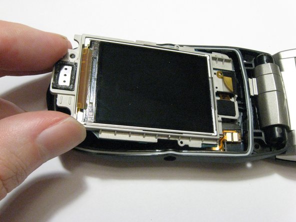
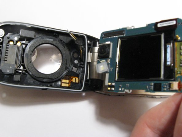
Pull the logic board out with a pry stick gently from bottom to top at the current orientation.
-
The ribbon cable will be connected underneath the logic board. A small amount of force is required to disconnect them.
-


Team

Clemson, Team 13-3, Benson Spring 2013 Mitglied von Clemson, Team 13-3, Benson Spring 2013
CLEM-BENSON-S13S13G3
3 Mitglieder
14 Anleitungen geschrieben