Diese Version enthält möglicherweise inkorrekte Änderungen. Wechsle zur letzten geprüften Version.
Was du brauchst
-
Dieser Schritt ist noch nicht übersetzt. Hilf mit, ihn zu übersetzen!
-
Find the battery compartment on the bottom of the clock radio.
-
Using your thumb, push the compartment cover latch toward the battery.
-
With the latch pushed in, pull the compartment cover upward to remove it..
-
-
Dieser Schritt ist noch nicht übersetzt. Hilf mit, ihn zu übersetzen!
-
Lift the battery from the compartment.
-
Pull the battery up and gently disconnect it from the battery connector.
-
-
Dieser Schritt ist noch nicht übersetzt. Hilf mit, ihn zu übersetzen!
-
Using a Phillips #00 Screwdriver, unscrew the six 12mm screws from around the bottom of the clock radio.
-
-
Dieser Schritt ist noch nicht übersetzt. Hilf mit, ihn zu übersetzen!
-
Gently pull the liquid crystal display (LCD) cover off.
-
-
-
Dieser Schritt ist noch nicht übersetzt. Hilf mit, ihn zu übersetzen!
-
Lift the top off. Two gray, plastic internal pieces will fall out when you do this; set them aside.
-
-
Dieser Schritt ist noch nicht übersetzt. Hilf mit, ihn zu übersetzen!
-
Using the wire cutters, carefully cut the plastic wire tie.
-
-
Dieser Schritt ist noch nicht übersetzt. Hilf mit, ihn zu übersetzen!
-
Grip the speaker.
-
Lift the speaker from the holder.
-
-
Dieser Schritt ist noch nicht übersetzt. Hilf mit, ihn zu übersetzen!
-
Locate the two 6mm screws on the PCB.
-
Using a Phillips #0 Screwdriver, unscrew the two 6 mm screws from the PCB.
-
-
Dieser Schritt ist noch nicht übersetzt. Hilf mit, ihn zu übersetzen!
-
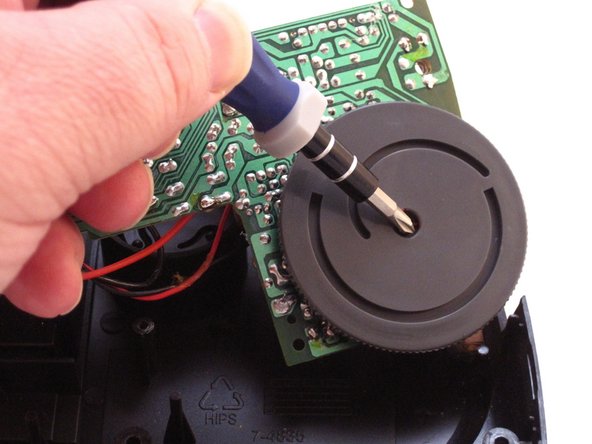
Raise the PCB to expose the AM-FM switch dial screw.
-
Using a Phillip's #01 Screwdriver, unscrew the one 3mm screw from the middle of the AM-FM switch dial.
-
-
Dieser Schritt ist noch nicht übersetzt. Hilf mit, ihn zu übersetzen!
-
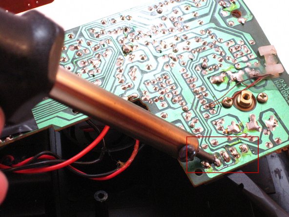
Locate the AM-FM pins on the PCB.
-
Carefully apply the hot soldering iron to the solder on top of the AM-FM pins.
-
Gently and firmly push on the pins with the Spudger to remove the switch from the underside of the PCB.
-