Diese Version enthält möglicherweise inkorrekte Änderungen. Wechsle zur letzten geprüften Version.
Was du brauchst
-
-
Drücke auf den Knopf auf der Unterseite der GoPro und schiebe die Akkuklappe zur Seite. Sie springt dann auf.
-
-
-
Ziehe und drehe die Objektivabdeckung nach rechts oder links, bis sie sich löst.
-
-
-
Schaue dir die iOpener Anleitung an, um zu erfahren, wie du den iOpener erhitzt und verwendest.
-
Lege den erhitzten iOpener für ein paar Minuten auf die Vorderseite der GoPro um den Klebstoff unter der Vorderseite zu lösen.
-
-
-
Benutze einen Spudger und hebele die Hauptplatineneinheit von der Seite des LCD aus ab
-
-
-
-
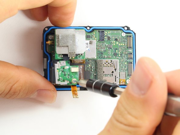
Benutze das flache Ende eines Spudgers, um die drei Flachkabel, welche an der Seite der Hauptplatine befestigt sind, zu entfernen.
-
-
-
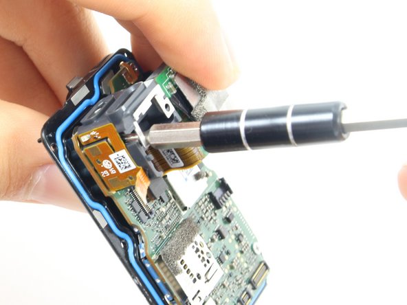
Benutze das flache Ende des Spudgers, um die Kabel des Akkugehäuses nach oben aus ihrer Buchse auf der Hauptplatine zu hebeln.
-
-
Dieser Schritt ist noch nicht übersetzt. Hilf mit, ihn zu übersetzen!
-
Use the flat end of the spudger to pry the black cover plate straight up from its socket on the motherboard.
-
-
Dieser Schritt ist noch nicht übersetzt. Hilf mit, ihn zu übersetzen!
-
Use the tweezers to pull the ribbon cable connector out of its white socket on the charging assembly board.
-
-
Dieser Schritt ist noch nicht übersetzt. Hilf mit, ihn zu übersetzen!
-
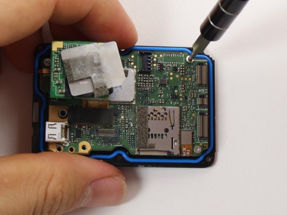
Remove the two #000 Phillips screw.
-
-
Dieser Schritt ist noch nicht übersetzt. Hilf mit, ihn zu übersetzen!
-
Use the flat end of the spudger to pry the charging port ribbon cable connector straight up from its socket on the motherboard.
-
-
Dieser Schritt ist noch nicht übersetzt. Hilf mit, ihn zu übersetzen!
-
Remove the 10mm #000 Phillips screw.
-
-
Dieser Schritt ist noch nicht übersetzt. Hilf mit, ihn zu übersetzen!
-
Remove the charging assembly housing by pulling it straight up off the motherboard.
-
-
Dieser Schritt ist noch nicht übersetzt. Hilf mit, ihn zu übersetzen!
-
Remove the two 6mm #000 Phillips screws.
-
Remove the two 2mm #000 Phillips screws.
-
-
Dieser Schritt ist noch nicht übersetzt. Hilf mit, ihn zu übersetzen!
-
Use the flat end of the spudger to pry the lens assembly ribbon cable connector straight up from its socket on the motherboard.
-
-
Dieser Schritt ist noch nicht übersetzt. Hilf mit, ihn zu übersetzen!
-
Use the flat end of the spudger to pry the LCD screen ribbon cable connector straight up from its socket on the motherboard.
-
-
Dieser Schritt ist noch nicht übersetzt. Hilf mit, ihn zu übersetzen!
-
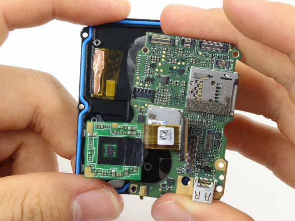
Use the flat end of the spudger to pry the motherboard off the midframe.
-


Rückgängig: Ich habe diese Anleitung nicht absolviert.
20 weitere Nutzer:innen haben diese Anleitung absolviert.
Team

Cal Poly, Team 18-6, Forte Fall 2016 Mitglied von Cal Poly, Team 18-6, Forte Fall 2016
CPSU-FORTE-F16S18G6
4 Mitglieder
22 Anleitungen geschrieben
11 Kommentare
Hi
I took off only faceplate. Do you guys have an idea how to make it waterproof again? What can be used as an adhesive? Thanks
you can try silicone glue, although obviously there is no guarantee to what extent it would be waterproof.
I used this guide to replace the USB port in my GP5. Does anyone know of a good way to hold the face plate down once it’s been removed? Not looking to make it waterproof again, just trying to hold the faceplate down a little better.
I would try either a silicone- or cyanoacrylate- (super glue) based adhesive. You can try to peel off the blue gasket and/or sand where the two pieces meet for better adhesion.