Diese Übersetzung enthält möglicherweise noch nicht die neuesten Änderungen der Original-Anleitung. Hilf mit, die Übersetzung zu aktualisieren oder sieh dir die Original-Anleitung an.
Einleitung
Diese Anleitung zeigt dir, wie du die Ladeeinheit austauschen kannst. Die Ladeeinheit enthält den USB-C Anschluss und ist am Vibrationsmotor angeschlossen.
Was du brauchst
-
-
Zum Entfernen der Kamerahalterung musst du sie erst erwärmen und dann mit einer dünnen Metallklinge vom alten Display abhebeln.
-
Das Lautsprechergitter besteht aus zwei Schichten — ein Gitter aus Metallgewebe und dahinter eine dünne Lage aus Stoffgewebe. Ziehe mit einer Pinzette beide Schichten gemeinsam vom alten Display ab. Trenne sie dabei auf keinen Fall voneinander.
-
Schneide zwei Ecken eines vorgestanzten Klebebogens so ab, dass keine Seite länger als 12 mm ist, oder schneide vier 12 mm lange Stücke von doppelseitigem Klebeband ab.
-
Bringe die Klebestreifen an Kanten der flachen Seite der Frontkamerahalterung an. Wenn du fertig bist, sollten an allen vier Kanten der Kameraöffnung Klebestreifen sein.
-
Drücke den Kleber vorsichtig mit einem Finger oder einem Spudger fest.
-
-
-
Setze die Kamerahalterung in ihren Schlitz um die Frontkamera ein.
-
Ziehe die weiße Schutzfolie von den Klebestreifen ab.
-
-
-
Verbinde den Displaykabelstecker des neuen Displays mit dem flachen Ende des Spudgers oder einem Finger.
-
Um Press-fit Verbinder wie diesen hier einzustecken, musst du erst eine Seite sorgfältig ausrichten und nach unten drücken, bis er einrastet. Wiederhole das Ganze für die andere Seite. Drücke nicht in der Mitte nach unten. Wenn die Kontakte nicht gut aufgesetzt sind, können sie sich verbiegen und dauerhaft beschädigt werden.
-
-
-
Richte die Unterkante des neuen Displays sorgfältig an der Unterkante des Smartphonegehäuses aus.
-
Setze zuerst das Display mit der Unterkante in das Gehäuse ab und klappe es langsam nach unten, wobei du auf die richtige Passung achten musst.
-
Setze das Display in das Gehäuse hinein und drücke an der Öffnung für die Frontkamera nach unten, so dass du sicher bist, dass die Halterung am Display festklebt.
-
Hebe das Display wieder vom Smartphone weg und überprüfe, ob die Kamerahalterung wirklich am Display festklebt.
-
-
-
Schneide ein etwa 3 cm langes Stück von 1 mm breitem doppelseitigen Klebeband ab.
-
Lege den Klebestreifen an der oberen Kante des Ohrhörer-Lautsprechers in deinem neuen Display entlang, so dass er mittig über dem Schlitz ist und die Oberkante berührt.
-
Drücke den Klebestreifen sorgsam mit dem Finger oder einem Spudger fest.
-
Befestige mit der gleichen Methode den zweiten gleichartigen Klebestreifen an der Unterkante der schlitzförmigen Lautsprecheröffnung.
-
Ziehe die weiße Schutzfolie von den beiden Klebestreifen ab.
-
-
-
Setze das Lautsprechergitter lose in seinen Schlitz ein, so dass die abgerundete Seite im Schlitz sitzt und die flache Seite vom Display weg zeigt.
-
Achte darauf, dass das Gitter mittig und richtig ausgerichtet im Schlitz drin sitzt, bevor du es nach unten gegen den Kleber andrückst.
-
-
-
Drücke die Kanten des Lautsprechergitters mit dem flachen Ende eines Spudgers oder deinem Finger gegen die Klebestreifen herunter.
-
Wiederhole die vorigen Schritte für das untere Lautsprechergitter.
-
-
-
Lege zwei Minuten lang einen erwärmten iOpener auf den Näherungssensor an der Oberkante des Mittelrahmens, so dass seine Klebeverbindung aufgeweicht wird.
-
-
-
Schiebe die Spudgerspitze unter das Kabel des Näherungssensors, fange damit an der Seite in der Nähe der Frontkamera an.
-
Hebe das Sensorkabel vorsichtig an der Kante an, bis der Sensor rechtwinklig zum Mittelrahmen steht.
This piece is actually glued down - heat and rubbing alcohol really helped as at first I couldn’t figure out why I couldn’t get it to move.
-
-
-
-
Ziehe das kleine Stückchen Klebeband zurück, welches die Schraube unter dem Ohrhörer-Lautsprecher verdeckt. Wenn andere Schrauben auch beklebt sind, dann ziehe auch hier das Klebeband zurück.
-
Entferne folgende Schrauben, mit denen der Mittelrahmen befestigt ist:
-
Elf 3,7 mm Kreuzschlitzschrauben
-
Eine 4 mm Torx T5 Schraube
On my Pixel 2, I also had to peel back a small strip of conductive tape that was directly above (and the same kind as) the “screw below the earpiece speaker” mentioned above. It appears to be a ground strap to the assembly underneath.
Me too! Please change the photo?
If you don't peel the mesh tape up, it will year. I'm not sure if it plays into the screen potentially not working, but it seems to be a ground for the midframe and the display ribbon has a ground contact to the
Many of the screws would not come out due to the original threadlocker on the threads. I found that if I just kept moving them around with a toothpick, I could get the out. I also had one of those telescoping magnetic bolt grabbers that pulled the screws out.
Would be nice if they included the correct torx bit in the tool kit... mine came with a T2 Torx...pretty useless...managed to get the display ribbon cable free as those screws were surprisingly not super tight - got them with the included Philips bit...pretty F$%^ED right here
@JensDavidsen, I'm sorry to hear that the kit came with the wrong bit. We do everything we can to make sure that our tool kits are kitted correctly. I've gone ahead and forwarded your information over to CS so they can get this fixed for you. In the future, if you have any questions or concerns, don't hesitate to reach out to us directly.
You will also need to peel up the grounding tape below the front camera from the right. Be careful about not being too aggressive else you might lose adhesion while putting it back. I used some glue to ensure it would stick again during reassembly.
What kind of glue did you use? I suspect that a) it could change the contact of the ribbon, therefore hindering conductivity and b) that the glue might change over time, e.g. break down and cause side-effects.
arne -
-
-
-
Setze ein Öffnungswerkzeug in die Einkerbung im Mittelrahmen in der Nähe der Halte-Taste ein.
-
Heble den Mittelrahmen so hoch, dass ein Spalt zwischen ihm und dem Gehäuse des Smartphones entsteht. Der Mittelrahmen kann noch nicht ganz ausgebaut werden.
This is to pop a securing tab out it's place
On re-assembly make sure the securing tab, near the notch you use to open it, is inserted back under the frame again - this caused me to have to re-open my phone as my screen didn’t sit back down properly after I had put everything back together.
It is more effort than I anticipated. I really thought I was going to break it, but it was fine.
-
-
-
Beginne an der Unterkante den Mittelrahmen hochzuheben.
-
Wenn der Mittelrahmen zum restlichen Smartphone einen Winkel von 45° erreicht hat, dann hebe ihn gerade nach oben weg.
-
Führe beim Hochheben des Mittelrahmens den Näherungssensor durch den kleinen Schlitz im Mittelrahmen.
While not shown here in the photo, there is a short braided cable between the midframe and the motherboard near the front facing camera that prevents separating the midframe completely (ground?). Be careful not to damage this cable when completing the remaining steps or carefully remove before trying to separate the midframe completely.
As ericdowens says above, there’s a small silver sliver of a connector (next to the front-facing camera). The guides on youtube said it was a grounding wire. This guide doesn’t mention it. Mine broke when I removed the midframe. No big deal. I stuck it back down with some tape when I put it all back together. Phone works fine.
I had a heck of a time levering up the midframe. I had popped the side with the opening tool, but the other side was really stuck. I used some alcohol along the edge thinking there was some adhesive. Not sure. I eventually used a dental pick to pop it loose.
And when reinstalling, don’t forget to move the short braided cable back out of the way so you don’t trap it inside.
STOP! Before you lift the midframe, the ground strap mentioned by ericdowens and Alex Lawson definitely will break if you don’t remove it from the midframe before lifting. I didn’t quite know what they were talking about, so thought I’d look for it as I was lifting the midframe, as I was sure if I was careful I’d spot it before it would break. I was very gentle, and I still broke it before realising what they were talking about. Look for some silver mesh tape on the midframe, near the forward-facing camera, same kind of tape as over the screw shown in Step 14. I’m going to try and carefully tape mine back together as Alex Lawson did, but it will be very fiddly, wish I hadn’t broken it in the first place!
I broke mine... then proceeded to pilfer about 2mm worth of the tape depicted in step 18 because it's a silvery adhesive.
-
-
-
Löse den Akkustecker mit dem flachen Ende des Spudgers ab.
This photo and tutorial doesn't show the shielding on the chips of the motherboard. And the glue…My pixel 2 had the volume button ribbon cable glued to the shielding. Carefully pry the cable off. Very carefully slide under it. Maybe use a little heat to soften the glue. You cannot just remove the motherboard with removing the ribbon cable for the volume buttons.
-
-
-
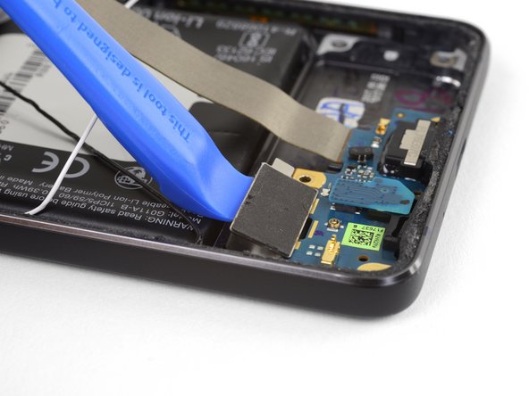
Trenne den Stecker der Ladeeinheit mit dem flachen Ende des Spudgers ab.
There is a metal cover not shown here that covers the motherboard, on it the charging assembly is glued with a little adhesive. To remove it apply heat with the iOpener or a heat gun and carefully pull it with an spudger or a tweezer.
-
-
-
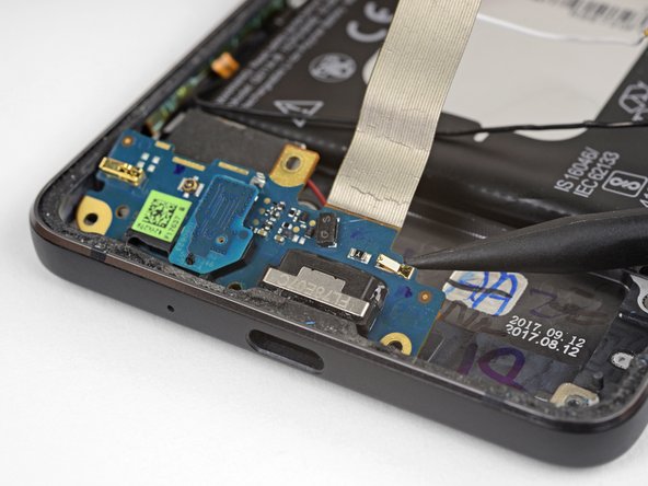
Heble den Stecker am weißen Antennenkabel mit der Spudgerspitze gerade nach oben und trenne es von der Ladeplatine ab.
-
-
-
Ziehe das weiße Antennenkabel mit einer Pinzette gerade nach oben aus den Metallklammern heraus und hole es aus der Rille auf dem Lautsprecher heraus.
-
Schiebe das Kabel zur linken Seite des Smartphones hin, so dass es dem Lautsprecher nicht mehr im Weg ist.
-
-
-
Heble den schwarzen Antennenkabelstecker mit der Spudgerspitze gerade nach oben und trenne ihn ab.
-
-
-
Hebe das schwarze Antennenkabel mit der Pinzette aus seiner Rille auf dem Lautsprecher heraus.
-
Schiebe das Kabel zur Oberkante des Smartphones hin, so dass es dem Lautsprecher nicht mehr im Weg ist.
-
-
-
Schiebe den Stecker am Lautsprecherkabel vorsichtig waagrecht aus seinem Anschluss heraus, indem du abwechselnd auf beiden Seiten des Steckers ein wenig mit der Spudgerspitze drückst.
This step is correct but does not explain the design of the socket or the process needed to remove it very well. The two wires enter a socket that has a very thin (you will need a magnifier to see it well) edge. This is what is pulled out horizontally from the circuit board socket. The socket base remains on the board. It would be 2000% helpful if there was a photo showing a close-up of the socket base from the socket itself - together in the same photo. The good news is if you are replacing the charging port, the new board will have a socket base into which you can plug your socket.
-
-
-
Heble die Lautsprechereinheit mit einem Plastiköffnungswerkzeug ein wenig aus ihrer Vertiefung im Smartphone heraus.
-
Halte das silberfarbene Kabel der Ladeeinheit bei dieser Arbeit aus dem Weg, achte aber darauf, dass es nicht zu stark verbogen wird, oder dass der Kontakt zur Ladeeinheit zu stark belastet wird.
-
-
-
Drehe die obere rechte Ecke des Lautsprechers zur Oberkante des Smartphones hin, wobei du die ganze Einheit nach rechts gleiten lässt.
-
Entferne den Lautsprecher.
-
-
-
Hebe den Vibrationsmotor vorsichtig mit einem Plastiköffnungswerkzeug an und löse ihn aus seiner Klebeverbindung zum Smartphone.
-
Versuche noch nicht den Motor zu entfernen - er ist immer noch mit der Ladeeinheit verbunden.
-
-
-
Kontrolliere nochmals, ob der Vibrationsmotor nicht am Smartphone befestigt ist. Hebe dann die Ladeeinheit vorsichtig aus dem Smartphone heraus, wobei du auch den Vibrationsmotor mit hochhebst.
In the last step, the microphone board is attached to the charging assembly and needs to be removed and placed on the new assembly when replacing.
I wish I could highlight your comment or get the original author to point this out in an image. I didn’t check this the first time through and had to pull the phone back apart to add the mic onto the new charging assembly.
(My mistake for not checking the boards against each other carefully - all other instructions were so thorough, I didn’t feel the need at the time to verify.)
-


Vergleiche dein Ersatzteil mit dem Originalteil. Du musst vielleicht fehlende Teile vom alten auf das neue Teil übertragen oder Schutzfolien vom Neuteil abziehen, bevor du es einbauen kannst.
Um dein Gerät wieder zusammenzusetzen, folge den Schritten in umgekehrterReihenfolge.
Entsorge deinen Elektromüll fachgerecht.
Die Reparatur hat nicht den gewünschten Erfolg gebracht? Unser Antwortenforum kann dir weiterhelfen.
Rückgängig: Ich habe diese Anleitung nicht absolviert.
14 weitere Nutzer:innen haben diese Anleitung absolviert.
Besonderer Dank geht an diese Übersetzer:innen:
87%

Diese Übersetzer:innen helfen uns, die Welt zu reparieren! Wie kann ich mithelfen?
Hier starten ›

3 Kommentare
I’m fairly disappointed with this. It didn’t say that the microphone chip had to be transferred to a new part. This caused me to take this phone apart twice.
Is the charging assembly PCBA really responsible for battery charging?
Or is it just supplying the 5V from the charger thru the flex to the motherboard, which is in fact responsible for the charging?
There are additional "data" pins on the battery, which I suppose are also used during charging to report battery temperature etc., but these pins are not directly connected to the flex connector.
So I think that the motherboard is responsible for charging.
My phone is not charging, but i can measure the 5V from the USB on the motherboard connector at the end of the flex. Will it help to change the charging assembly?