Einleitung
Diese Anleitung wurde von iFixit-Mitarbeitern erstellt und nicht von Google unterstützt. Erfahre hier mehr zu unseren Reparaturanleitungen.
Die Anleitung zeigt dir, wie du eine defekte Displayeinheit im Google Pixel 3 austauschen kannst. Diese Anleitung ist für Ersatzdisplays, die nicht auf einem Rahmen vormontiert sind. Das Pixel 3 ist so aufgebaut, dass die Hauptplatine ausgebaut werden muss, um an die Displaystecker heranzukommen.
Beim Ausbau des Displays im Pixel 3 wird das Display zerstört. OLEDs funktionieren nicht mehr, wenn sie Sauerstoff oder Feuchtigkeit ausgesetzt sind. Sie sind deswegen luftdicht eingeschlossen. (Das ist auch der Grund, warum OLEDs an Bruchstellen schwarz werden). Das Frontglas alleine zu tauschen ist sehr schwierig, weil die OLED-Schicht fest mit dem Glas verbunden ist.
Was du brauchst
-
-
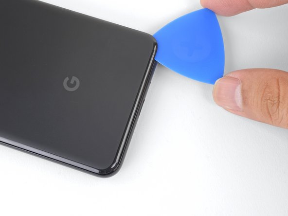
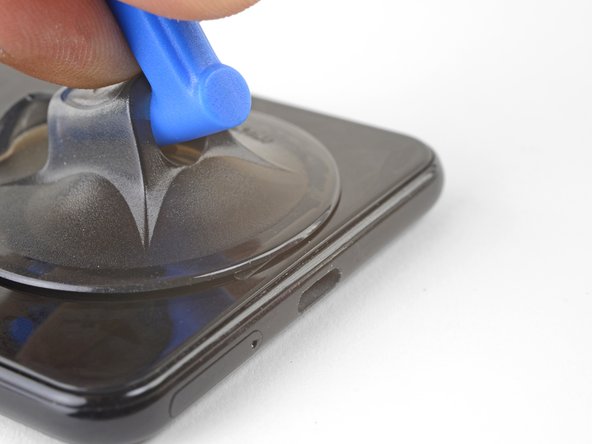
Erwärme einen iOpener und lege ihn eine Minute lang unten auf das Smartphone auf.
-
-
-
Bringe einen Saugheber am erwärmten unteren Rand der Rückseite an.
-
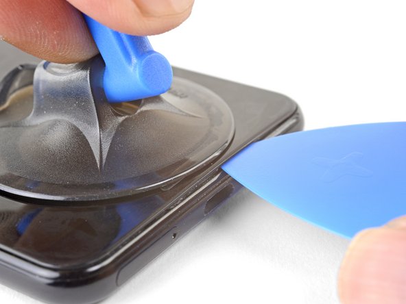
Hebe den Saugheber kräftig und gleichmäßig nach oben, bis ein Spalt entsteht.
-
Setze ein Plektrum in den Spalt ein.
The initial opening/insert is the hardest part of this repair, and if you end up having to use a flat-head screwdriver (etc) to get the first gap opened, you’ll scratch the phone. But it works.
I don’t recommend using a screwdriver. I tried this and it shattered the glass in that area. I replaced the battery on my Pixel 1 recently and noted that heating the FRONT glass on that phone enough to get a gap for one of the pics takes a considerable amount of time AND patience. I was one of the few who didn’t break or otherwise damage the glass in that process. I would say the same rule applies here. Allow for significant time and patiences to heat the old adhesive enough to get a pick inside the cover.
Definitely, this opening/insert is the hardest part of the procedure. I was unable to open even a slight separation with a suction cup and even with tons of heat from a hair dryer. What worked really well, and what I would highly recommend to others who experience really strong adhesive, is to use a small X-acto knife with a #16 blade. Make sure it’s a #16 (find on Amazon) because it differs greatly in angle and rigidity from the usual #11 blade. The sharpness of the blade makes it really easy to find the crack and open a gap, where you can then insert a pick with no problem.
I used a typical razor blade (like Matt and Rick and Greg) pressing the whole of the blade against the edge (blade parallel and flush against the back cover). The razor slipped under enough that I could get a pick in. (No damage, but when I first tried the corner of the razor, a small cut was immediately evident. Only use the whole blade.) Then, I used blue picks exclusively.
I'm very curious about the dental floss method. I'll try that if I need to get back inside.
I really wanted to level off the back of the phone when pulling on the suction cup in this step, but found it was actually pretty easy once I used the opening tool to push down on the edge of the bezel, at the crack, barely putting any force on the back of the phone at all (just to keep it steady).
I have about a 2 year old Pixel 3. iOpener didn’t work at all on this step, but once I broke out the hair dryer, I was able to get the phone hot enough to insert the pick (no screwdriver or xacto knife needed)
I’m having trouble with the iOpener too. It is frustrating because I practiced on a bricked iPhone earlier this week and it was effortless. My Pixel 3 is also about 2 years old. Out of curiosity, were you replacing the charging assembly because of the charging cables fitting too loosely on the phone or for some other reason?
Edwin -
I used a stanley knive to get started and then a combo of opener and plektrums.
All went well till I used to much force on the camera corner and broke the back into lots of small pieces. Be careful on that corner, people.
But the new camera does focus, so for a first attempt at fixing a phone I am happy.
I heated the bottom up with the Iopener and then used a rectangular razor blade and the suction cup to lift the bottom. Place the entire blade edge into the crack and push/pry while lifting with the suction cup. As soon as you have a gap start to open, have a second person insert a pick into the corner. It was actually really easy. I had given up after a couple of tries without a blade. My Pixel 3 is 2 years old.
Agreed with many other comments here. My Pixel 3 is two years old and neither the iopener nor a blow dryer were capable of loosening it enough. I ended up using a VERY hot iopener for a couple of minutes, the suction cup, and then a wide-bladed razer blade (about 80% width of bottom edge to spread out the stress and prevent risk of fracturing the rear glass panel). Once adding the razer blade I was able to get the pick in and follow the rest of the instructions as written.
I also had to follow this process but resorted to a heat gun on its lowest setting as I couldn’t get the iOpener hot enough (I was afraid of overheating and bursting it). Other how-to videos also show using a thin piece of plastic or metal to slide into the corner, saving substantial time.
Helped me to notice that the focus here is to lift in the center (like right over the USB C connector). Was able to get it with just the iOpener and pushing down on the rest of the phone with the pry tool. My phone is over 2 years old though and it took about 50 minutes of working / reheating / repeating
Destroyed the glass back trying to take it off. This is not an easy phone to take apart.
It would be nice if there was a heads up that the rear of the phone is glass….. Phone piping hot glass shattered and splintered
Hi John!
Good suggestion! I'll add that into the step.
The Jimmy tool from the iFixit toolkit worked like a freakin’ charm. Took me 10 mins to open the phone and it came out unscathed.
I used dental floss to cut the adhesive and slide it open. Just wiggle it back and forth from the corners until you cut enough that you can switch to a pick. Helps to have a extra hand to hold the phone.
Brother, dental floss was an absolute godsend!!! After 4 hours with the IOpener and attempting to use a heat gun which I balked from out of fear I came across this comment. Teased it around a corner and was then able to saw away at the adhesive. A lot of patience but no heat or potentially damaging tools needed. Thanks!
With the floss, I wasn't getting enough "sawing" motion as it just slipped through my fingers too easily (my phone is about 4-5 years old I think, I bought it used). So I tied a few knots around a pen (the kind with a gripper, so the floss won't slide off) and it was a lifesaver. After about 3 hours trying other ways, the floss/pen saw got it open enough to stick the picks in and eventually open it up!! Thank you to everyone who commented these tips!!
I have a 2-3 year old phone. The “heating pad” and blue picks did not work. I tried for two hours. Two weeks later I tried again using a hair dryer on high heat and low fan, and a rectangular utility razor blade. Start at the bottom of the phone, heat, and insert the razor blade into the gap and use it to cut the adhesive back a little at a time. Do not insert it more than about a 1/4 to 3/8 of an inch. Once you start getting a separation, use the blue picks to hold it open. Go up both sides an inch or two on both sides at a time. Do not pry the back open more than an 1/8 of an inch or so until you get it separated all the way around. Be patient. Work slowly. This took about 30 minutes once I got the hang of it. Do NOT pull the cover away from the phone after you separate it all the way around!! Read the instructions several times. There is a cable to the finger print sensor attached to the cover!
Re-read these entire set of instructions and ALL of the comments TWICE before you start.
I used and iOpener and the iFixit tool (the one with the metal spatula). Ended up inserting about 10 picks, but it worked.
I couldn’t get the pick in so I tried the sharper pry tool. Got it in and slid it sideways towards the corner —- BLAM, the back shattered. Not a good home repair experience.
Similar experience with others, iOpener would not heat up the phone enough to separate the adhesive. Had to use a hair dryer to finally insert the blue pick. After sliding the pick past the corner, the back glass scattered… Time to get a new phone and give up on this battery replacement i guess.
On a 3 years old Pixel 3 phone, after unsuccessfully trying iOpener and the suction cup, I used a piece of dental floss, and it worked perfectly.
To make the process easier - tie little loops on both ends of the floss, put a finger or a screwdriver through the loop to help pulling the floss. Pull it through to one side and then to another, continue until you’re 1/2 inch in. At this point it should be possible to insert a pick
This was the hardest step. I could not get the pick in at all. I tried dental floss and it slid in no problem. I eventually stuck the very tip of a razor blade in which allowed me to slide in a pick. Also be very careful when sliding the picks around as my wife broke the back glass of her phone, try to keep pressure as even as possible without bending the glass much.
I like the dental floss idea. I set edges of the phone-back and also the blunt metal tool on an electric cooktop on low heat, and the adhesive softened enough to be workable. SAFETY TIP: the tool and phone were hot to touch, I wore cotton gloves throughout this task.
Can confirm, with a 4-year-old Pixel 3, it was not possible to get the back cover off with any amount of force, heat, and the blue picks. I managed to get started by using single-edge box cutter razor blades and a hair dryer on high--got in just a bit under the left corner, then added a second blade along the bottom edge, and a third near the right corner, and that gave me enough space to get a blue pick in and start replacing the razors with blue picks one by one, and then proceeded as per the instructions. Dental floss is a neat idea; I wish I'd tried that--the razors didn't do any damage, but I was worried about the possibility.
Agreed; a 4cm section of utility knife was required along with heat/alcohol/patience to break the initial seal.
Managed to do it without cracking anything, but sweated through this step quite prolifically.
Mike -
3.5 year old phone. Just wanted to confirm that dental floss, combined with the iOpener, does the trick to get the first pick in.
I was able to slide the floss under the bottom right corner if you are looking at the phone. I alternated between sawing with the floss and applying heat with the iOpener. Eventually I was able to get a pick in that corner and was able to remove the rest of the adhesive by applying heat with the iOpener and sawing with additional picks around the perimeter of the phone.
My Pixel 3 is 4 years old. I tried using the iOpener heat pad for 2 minutes. Didn't work. Then I tried using a heat gun on low for about 30 seconds. Didn't work. Then I used the heat gun on high for about a minute, then the suction pulled it off. I used the picks to peel the rest off. I thought about using the floss which would have work well. I also though about letting the phone sit in the car when it's hot outside. The key is to be patient and try not to use something besides the plastic tools. If I can do it then anyone can. Heat guns are very cheap and a good tool to have.
After unsuccessfully trying all prying tools including metal ones - I finally hit the motherlode with the most inane thing possible-a stiff plastic collarbone-it has a slight angle at one end that gives it the required amount of rigidity and prying power.
Yes, a heat gun is an absolute must!
I've ordered the battery replacement kit, it will arrive next week. I keep my house cool in fall/winter, so I'm a bit concerned about how well I'll be able to heat the adhesive. I'm considering heating the whole phone in my convection oven's "warm" function. Its thermostat compares well with a meat thermometer, I might try my lab grade thermometer too.
I see "The phone is designed to work best in ambient temperatures between 32° and 95° F (0° and 35° C), and should be stored between ambient temperatures of -4° and 113° F (-20° and 45° C)." 113° F seems pretty low, perhaps that's when the adhesive begins to soften appreciably. I was considering starting at 120F. (And trying "toast" if it defeats me.)
Experience, suggestions, good luck wishes welcome.Hi reg!
The temperatures you listed are operating temperatures—once the Pixel exceeds those temperatures, it will shut down and show a heat warning symbol. Ideally, you want to heat just the adhesive perimeter. The back cover should be slightly too hot to the touch—aim for about 80°C.
3.5 year old phone. Thank the gods you guys recommended floss. I broke 2 nails trying the picks. Unfortunately I used extra slippy floss so I couldn't even tie it into loops to help. Even with the floss I couldn't saw my way through or get a pick in so I ended up just adding more and more floss (and more and more hairdryer) until I could get the pick in. After that it was just careful muscle.
Despite several frustrating tries across several days, I had zero success creating a molecule of seam gap to begin to remove back cover without breaking it! Suction cup ineffective (needs 3rd? hand to pull-and-insert pick); heated iOpener doesn't U-fold to cover perimeter (soon cools off in 63F room); hair dryer likewise too-brief heat; Exacto or utility knife blades useless. Dental floss no luck. But only! once I tried keeping the Px3 on my electric 1980s food warming tray (Lo heat ..hands resting on insulating hot pads ..it also! keeps iOpener hot) ..would dental floss fit into corners (No chance midpoint at charge port per foto); then blue pick. But! floss was too slippery to pull/grip strongly ..one must tie loops at each end, then use old-style 'peg' clothespins (or pen with clip) to roll-up floss length to enable pulling right at insertion point. With fingers/hands preoccupied manipulating floss, it was awkward to simultaneously tug suction cup upward effectively at all. Didn't break rear cover ;-)
I had no luck with just a suction cup and heat. Heat and a razor blade as others commented worked well; HOWEVER, while working the blue opening picks around the bottom I cracked the glass. The back glass is more delicate than I anticipated. :-( Be very careful/gentle with the back glass! If I attempt this with another glass-backed phone I will plan to work on an actively heated pad for this step.
The plastic opening pick was to thick to get into the (almost nonexisting) crack. I had to use a thin sharp metal knife, which scratched the paint a little bit but finally made the crack wide enough for the plastic pic to fit in and finish the job. Perhaps one thin metal pick would be helpfull in the kit for this first step.
As others have said, this step was by far the most difficult and time consuming. DO NOT RUSH THIS STEP THOUGH. Take it slow and do NOT bend the back glass to try and speed things up. Keep slicing your way though, patiently being aware of the fingerprint sensor cable. On my phone it required a lot of force and im not even sure the puller was able to make a gap.. I found that the plastic picks were too thick to get a crack started. I ended up using a piece of plastic from a clamshell plastic container to finally make it through the crack and through the adhesive. I tried the plastic backing of one of the adhesives but that wasn't rigid enough. Once though I made my way about half way through; and in haste I made the fatal mistake of bending the back glass to much and shattered it. Yes it is in fact made of glass! It will NOT BEND. I ended up getting a replacement back glass kit on Amazon for $16 which had a new sensor and the adhesive pre-installed which was very nice.
-
-
While the text is accurate, I found this image to be misleading - it appears as if the finger print cable is attached to the right side (from a back-of-phone reference). Only upon close image inspection is it clear that the cable has already been disconnected from the connector that is positioned just inside and above the power button.
-
-
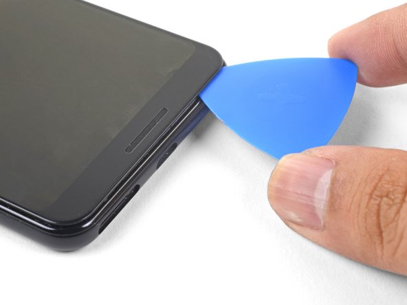
Trenne den Kleber an der Unterkante des Smartphones und um die rechte Ecke herum auf.
-
Lasse ein Plektrum in der Unterkante stecken, damit sich der Kleber nicht wieder verbindet.
The back cover is glass! I was sure it was some kind of nice plastic. It's probably obvious to a lot of people, and it's very obvious in hindsight, after shattering it. But I'm writing this in case anyone else is oblivious to the last decade of smartphone design. I got impatient and flexed it out as I cut the glue. Don't do that. Carefully work your way around and avoid applying any significany bending forces to the cover.
Yup, shattered the back of my phone while trying to follow these instructions. You can’t flex the back cover much at all or it is toast.
Someone else had said to use floss to start the cutting I found this to be the most useful. After I heated the phone with a hairdryer I would cut some of the adhesive at the bottom corner after sawing away for a bit I was able to move it enough to fit one of these picks in then I slowly reheated around the edge as I slowly moved more picks and slowly cut away at the adhesive .
Didn't have guitar picks. I grabbed some plastic packaging from my recycle bin and cut it into a bunch of triangles to hold the gap open as I worked my way around.
Leaving the pick in the bottom as described while using another to slide up for the next steps shattered the back cover - these instructions should be clear to only leave the pick in the bottom with as little inserted into the phone as possible as it does not take much flex at all to shatter. Also beware that there are no replacement back covers available from iFixit either :(
-
-
-
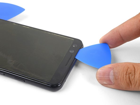
Erwärme die rechte Kante mit einem iOpener und trenne den Kleber weiter mit dem Plektrum auf.
What is the required temperature to soften the glue? Can I just use a small bag filled with boiling water or a heat gun.
The iOpener is a plastic bag filled with what appears to be water so probably, yes.
-
-
-
Erwärme ringsherum das ganze Smartphone und trenne weiter auf. Lasse in jeder Kante ein Plektrum stecken, so dass sich der Kleber nicht wieder verbinden kann.
-
-
-
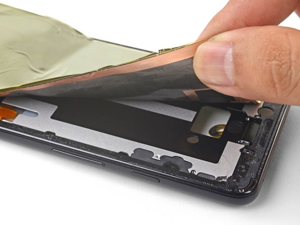
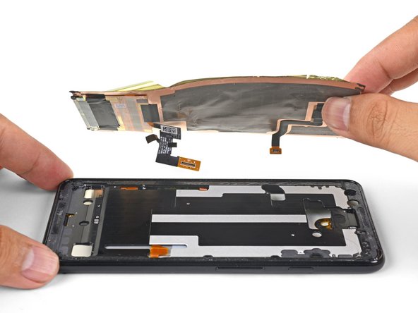
Wenn du den Kleber ringsum aufgetrennt hast, dann hebe vorsichtig die linke Kante der Rückabdeckung an.
-
Klappe die Rückabdeckung entlang ihrer langen Achse um und lege sie so hin, dass das Kabel zum Fingerabdrucksensor nicht angespannt wird.
Yes, per Step 7 foto, lift rear cover to vertical only! along the left edge (camera, power/volume) ..while also keeping the opposite long edge down (almost touching wireless coil) ..as left/camera edge rises (and right/lower edge slides leftward), take care to keep lower/right edge no further rightward than midway across coil (foto) ..then gently rotate now-lower right edge leftward 'clockwise', lay it flat without straining cable. [When my rear cover eventually suddenly released from the perimeter adhesive while still pulling on it, the upward force almost yanked the cover off cable; got lucky]
[this updates my minutes-ago post ..apparently one can't edit after 5min? ..or delete/replace with this?]
-
-
-
Entferne die beiden 4,1 mm langen Kreuzschlitzschrauben, mit denen die Halterung des Steckers des Fingerabdrucksensors befestigt ist.
A magnetic screwdriver tip helped here.
If you purchase iFixit’s kit for this replacement, their included driver is magnetic. Helped immensely!
after replacing my camera, my screen had a big green/white vertical stripe. I didn’t see the disclaimer about overtightening these screws. I think it may be related.
-
-
-
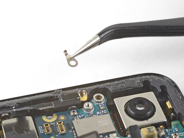
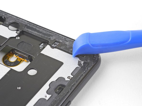
Lasse die Halterung des Fingerabdrucksensors mit der Spudgerspitze unter der NFC-Spule herausgleiten.
-
Entferne die Halterung des Fingerabdrucksensors.
Re-inserting this is tricky and requires pretty good dexterity. The shiny metal frame of the wireless charger is also not held down, so you may wish to gently apply pressure to it as you try to re-position the connector bracket.
I could use a whole tutorial on how to reinstall this
-
-
-
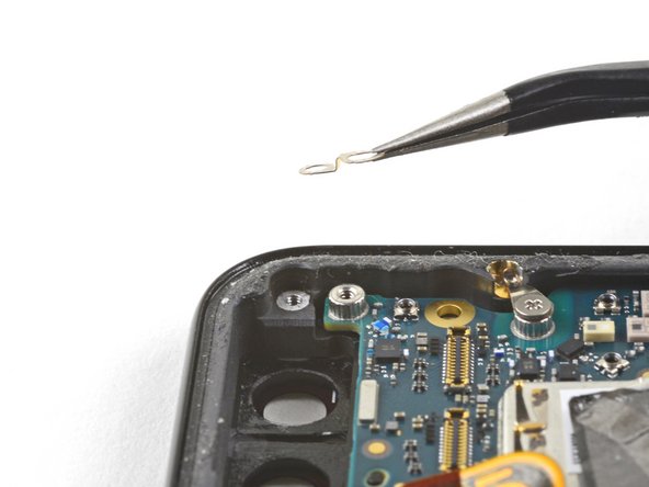
Heble den Stecker des Fingerabdrucksensors mit der Spudgerspitze hoch und löse ihn aus seinem Anschluss heraus.
-
-
-
Entferne die Rückabdeckung.
When reassembling is it better to first attach the new adhesive back gasket to the phone back or the phone chassis frame?
Hi Tom!
It depends on the adhesive. Carefully align the adhesive to the phone by matching the contours. Note which adhesive side is backed by a clear liner, and which side is backed by a colored liner. The clear liner should be removed first. Whichever component the exposed adhesive faces should be the first surface to apply to.
Hope that helps!
Two things:
1) I recommend attaching the adhesive to the Phone frame and not the back panel. As you attach, you can more easily see the gaps and guide the adhesive along the groove, leaving equal space all around.
2) To transfer the fingerprint sensor, you will need double-sticky tape to make a new gasket. Put the tape on the back from the inside, and trim with a blade to make the sensor hole. To attach the sensor, place it on something small to raise it off your working surface, then lower the back over it. You’ll be able to see the sensor alignment as you lower the back, which helps get a good position.
Oh, and be prepared: Removing the old adhesive is teeeeedious!! It will take you some time. :-b Alcohol is not a strong solvent, so don’t expect it to remove much; it is mostly for cleaning afterward. In the end, I used one of iFixit’s flat metal tools from the big toolkit to remove the final remains. Its was blunt enough to not cut metal shavings as I cleaned.
I used “medicinal” 91% Isopropyl Alcohol and about 30 Qtips to do the final cleaning of the adhesive, that is, after using a razor blade and the supplied tweezers to remove most of the tape. Patience and many Qtips soaked in IPA removed most of the remaining glue and film.
Greg B -
I ended up reusing the original adhesive as it was in pretty good shape. So far, no problems.
Does your IF356-119-1, Google Pixel 3 Rear Cover Adhesive, template use 2 sided pressure sensitive tape? Do I simply align it on the back cover and then press it to the device to reassemble the unit? If so, how long til the back cover is “glued” to the unit?
Hi Martin,
The rear cover adhesive is indeed two-sided PSA (pressure sensitive adhesive). Apply firm even pressure for a minute to bond the adhesive to the unit.
When scraping the adhesive off the back cover be careful and don’t apply too much pressure (and/or position the cover against the surface so that it’s supported against the tool used), especially in the corners, or the glass cover rounded edges could break.
Agree. BEWARE of SCRATCHING off the PAINT from the BACK COVER when cleaning !
The back cover is painted glass it seems - using a razor blade to scrape off adhesive also scratches off the paint on the inside of the back cover, under the adhesive, and the clear lines it creates are visible from the outside of the back case. If you are using a phone case, this won’t matter.
Greg B -
My battery swelled and did all the hard work getting started popping the back open so I didn’t need the iOpener to get the back off, but now the iOpener is handy to heat up the sticky foamy factory original adhesive.
I found isopropanol ineffective. I found heat softens it considerably. Just very warm, like hot water warm, is effective. Use tweezers or a plastic blade to help pull it off. Metal blades will either gouge the plastic or, worse, create metal shavings that will wreak havoc.
Are there any solvents other than isopropanol that work and won’t harm the plastic? How do pros speed up this step?
I think pros often use heating pads or special jigs. They’d set the temperature, set the phone on the pad, and let the phone heat up for a few minutes. Heat guns are also a popular choice.
I found that an opening pick worked well to scrape the glue off the inside of the curved edges of the back cover
The adhesive on mine took some effort to clean off all the way. During reassembly I did notice that my replacement back panel adhesive was larger than I expected and based off of product photos it looks like I received the 3 XL adhesive instead of the 3. That ended up having me fiddle with the adhesive to try and get it to fit right and unfortunately the camera side now has a bit of a gap that I can still press down on without having it stick. I’ll see how it stays but I fear I might have to get another adhesive. The guide was very helpful though!
The actual back glass cover part is missing from the parts list and it appears iFixit doesn't sell it anymore.
It used to be there, and I ordered one months ago and used this guide successfully then. I broke it again and the part is no more.
-
-
-
Entferne die fünf Kreuzschlitzschrauben, mit denen die kabellose Ladespule befestigt ist:
-
Zwei 1,9 mm Schrauben
-
Zwei 4,2 mm Schrauben
-
Eine 4,3 mm Schraube
The top 1.9 mm screw can’t be totally removed — it comes out with the coil once loosened
This was not true for me.
Can I leave the wireless charging coil out?
This may also allow a bigger battery!
You may be able to! Note that this is not only the wireless charging coil, but also the NFC antenna (the upper loop).
The 1.9 mm screws are actually screwed into the head of another screw beneath them. Sometimes the lower screw unscrews instead of the upper. That leaves both screws attached to the coil. If possible you should separate the two screws and screw the lower one back in first using a small flat blade screwdriver.
If you decide to clean the wireless coil assembly, be aware that IPA will completely remove the printed 2-D barcode on the lower right. (Hopefully that's not important.)
There were 7 screws!!! The last two were both near the power button.
Yes, I have that to, and a little black plastic part covering I port.
l won’t mother board google pixel3 contact on WhatsApp +250783996430
-
-
-
Hebe die kabellose Ladespule hoch und entferne sie.
There seems to be a small amount of adhesive holding down the camera-side edge of the coil. Used a spudger to peel it off...and some of the black film on the back side of the coil was torn away.
Had some adhesive tape holding down the camera side of the coil. Used the tweezers and the spudger to carefully peel it off.
Also has some adhesive from the back cover edge that caught on the black film at the top of the phone (above NFC coil) - VERY carefully scraped it off with the point of the spudger while gently pulling the coil assembly away. -
-
-
Heble den Druckstecker des Akkus mit der Spudgerspitze aus seinem Anschluss nahe der rechten Kante des Smartphones hoch und trenne ihn ab.
The connecton board is quete flexible … be careful otherwise other connectors may get looze.
This is also valid when re-assemble … pusing battery conector may cause other conectors to “pop“.
The square connector directly below the battery connector came undone and will not pop back into place.
-
-
-
Entferne die beiden Schrauben, mit denen die Kamerahalterung befestigt ist:
-
Eine 4,1 mm Kreuzschlitzschraube
-
Eine 4 mm Abstandsschraube
-
Entferne die Kamerahalterung.
-
-
-
Die Normalkamera
-
Die Weitwinkelkamera
Make sure that the cameras each go in exactly the same spots or not the phone will boot loop forever. The connectors on both of these cameras are the same, so they will easily connect on both sides. So be careful.
-
-
-
-
Heble mit der Spudgerspitze den oder die Stecker der Kamera (s), die ersetzt werden soll(en), hoch.
-
-
-
Setze eine Spudgerspitze hinter die Kante des Kameramoduls ein und heble hoch, bis es sich vom Rahmen ablöst.
-
-
-
Entferne die Kamera(s) mit einer stumpfen Pinzette.
-
-
-
Heble den Lautsprecherstecker mit der Spudgerspitze hoch und löse ihn aus seinem Anschluss auf dem Motherboard in der Nähe der rechten Kante des Smartphones.
-
-
-
Entferne folgende vier Kreuzschlitzschrauben:
-
Eine 1,9 mm Schraube
-
Eine 4,3 mm Schraube
-
Zwei 4,3 mm Schrauben mit dünneren Schäften
-
Entferne die winzige Erdungsklammer vom linken Schraubenloch. Verliere sie nicht.
-
Entferne den kleinen Kunststoffeinsatz von der rechten Seite des USB-C-Anschlusses.
The three 4.3 mm screws highlighted in Orange are not all the same. The one closest to the battery is slightly different, a larger diameter. It would be good to note this for reassembly.
Thank you! I will adjust the guide to reflect this!
Ah, all great and everything but this should be in big bold red letters: “Be sure to reinstall this insert before you screw down the daughterboard.“
Screwed 4.3 thin screw without that small insert and penetrated new screen module behind…
Noted and changed!
-
-
-
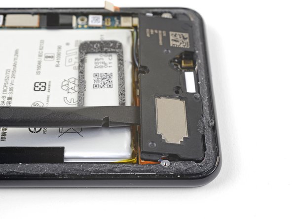
Setze die Spudgerspitze unter die untere rechte Ecke des Lautsprechers ein.
-
Heble nach oben, um den Lautsprecher vom Smartphone abzulösen.
-
-
-
Setze die Spudgerspitze unter die obere linke Ecke des Lautsprechers ein.
-
Heble nach oben, damit sich der Lautsprecher löst.
-
-
-
Setze das flache Ende des Spudgers unter die Oberkante des Lautsprechers in Richtung der linken Kante ein.
-
Heble nach oben, damit sich der Lautsprecher löst.
-
-
-
Entferne den Lautsprecher.
-
Wenn sie noch in gutem Zustand ist, dann kannst du sie weiter verwenden. Achte darauf, dass die Dichtung nicht die Ausgangsöffnung verschließt.
-
Wenn sich die Dichtung nicht mehr an ihrem richtigen Platz befindet, dann entferne sie und ersetze sie durch vorgestanzte Klebestreifen oder Tesaband.
tesa tape seems hard to come by in my town. Is there anything else I could use?
Never mind. A bunch of tesa tape came with the kit
Adhesive is VERY strong. Used the Ifixit opening tool on the uppder edge between battery and speaker to get better leverage without risking cable / board underneath or the battery.
-
-
-
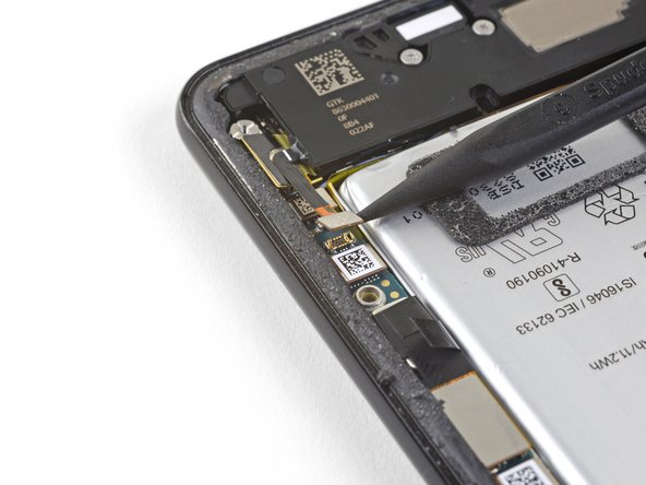
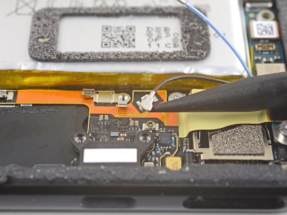
Heble das blaue Antennenkabel mit der Spudgerspitze hoch und löse es aus seinem Anschluss auf der Ladeeinheit.
-
-
-
Heble das blaue Antennekabel sorgfältig hoch und löse es aus seiner Erdungsklammer heraus.
-
-
-
Heble das schwarze Antennenkabel mit der Spudgerspitze hoch und löse es aus seinem Anschluss nahe beim USB-C Port.
-
-
-
Fädle behutsam beide Antennenkabel aus und biege sie von der Ladeeinheit weg.
-
-
-
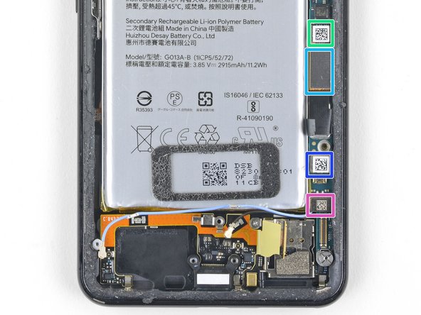
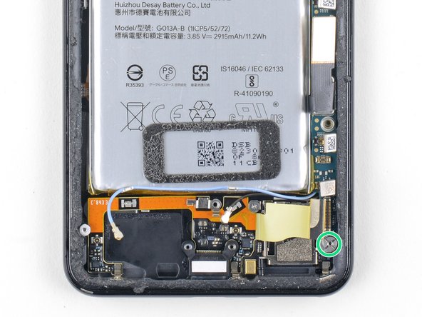
Heble den Stecker der Ladeeinheit mit der Spudgerspitze hoch und löse ihn aus seinem Anschluss auf der Hauptplatine nahe am rechten Rand des Smartphones.
-
Ziehe vorsichtig das Flachbandkabel von der Oberseite des SIM-Kartenlesers ab.
-
-
-
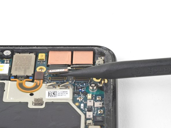
Heble sorgfältig mit dem flachen Ende des Spudgers das schwarze Klebeband hoch, mit dem das Displaykabel nahe an der rechten Kante des Smartphones befestigt ist.
-
Heble den Displaystecker mit dem flachen Ende des Spudgers hoch und trenne ihn von der Hauptplatine ab.
-
-
-
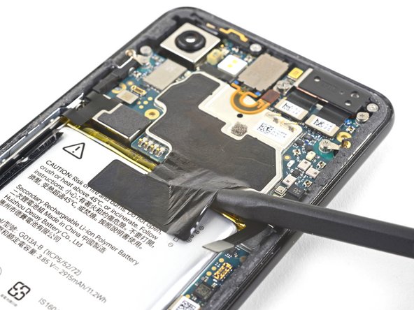
Schiebe die Spitze des Spudgers in den Spalt unter das schwarze Klebeband, das über den Akku und das Motherboard geklebt ist.
-
Schiebe den Spudger entlang des Spaltes um das Klebeband von der Akkuseite anzuheben.
-
Entferne vorsichtig das Klebeband vom Akku und falte es aus dem Weg.
-
-
-
Heble mit einem Spudger folgende sieben Press-fit-Verbinder hoch und löse sie aus ihren Anschlüssen auf der Hauptplatine:
-
Verbinder zu den externen Tasten
-
Verbinder zum oberen Mikrofon
-
Verbinder zum Ohrhörer
-
Verbinder zum linken Drucksensor
-
Displayverbinder
-
Verbinder zum rechten Drucksensor
-
Verbinder zum SIM-Kartenleser
Note the "screen connector" mentioned here SHOULD refer to the smaller, upper screen connector. The one indicated here was already disconnected in step 31.
-
-
-
Heble behutsam das Flachbandkabel zum Ohrhörer-Lautsprecher mit dem flachen Ende des Spudgers hoch und biege es nach oben, so dass es der Hauptplatine nicht mehr im Weg steht.
I STRONGLY recommend simply REMOVING the phone speaker at this step. It is VERY easy to damage the flex cable when removing the motherboard if the speaker is left in place. Removing the speaker entirely takes only a few seconds. Just be sure to replace the adhesive when re-installing. TESA tape works fine here.
When re-installing, make sure you remember this part when putting the motherboard back in. I followed the steps in reverse order, as suggested, and almost damaged the orange flex cable when I pushed it down.
-
-
-
Entferne die sechs Schrauben, mit denen die Hauptplatine befestigt ist:
-
Eine 4,2 mm Kreuzschlitzschraube
-
Drei 1,9 mm Kreuzschlitzschrauben
-
Eine 4,3 mm Kreuzschlitzschraube
-
Eine 3,83 mm Distanzschraube
-
Entferne die drei Erdungsklammern und bewahre sie gut auf.
During reassembly, don’t forget to replace the plastic piece before placing the 4.3mm screw.
-
-
-
Entferne die Antennenhalterung von der oberen linken Kante des Smartphones.
-
Lege die Erdungsklammern so ein, dass die silberfarbene Seite nach oben zeigt.
-
Die Spitze der tropfenförmigen Klammern muss zur Kante des Smartphones zeigen.
-
Die Klammer mit zwei Löchern taucht nach unten in das Schraubenloch oben rechts am Rahmen ein.
-
-
-
Setze die Spudgerspitze nahe der oberen linken Ecke der Hauptplatine ein, genau unter der Rückkamera.
-
Heble die Hauptplatine vorsichtig hoch, wobei du alle Flachbandkabel behutsam wegbiegen musst, um die Hebelbewegung zu erleichtern.
-
Wenn die Hauptplatine immer noch festsitzt, dann überprüfe, ob sie vielleicht noch durch Flachbandkabel oder Schrauben befestigt ist.
-
-
-
Setze den Spudger unter die Oberkante der Hauptplatine ein und heble vorsichtig hoch, bis sie sich löst.
-
-
-
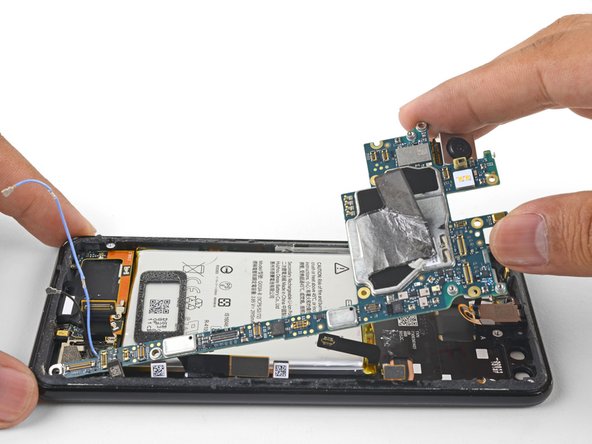
Hebe die linke Kante der Hauptplatine hoch und klappe sie vorsichtig hoch nach rechts. Drücke sorgfältig alle Press-fit-Verbinder, die noch an der Hauptplatine festhängen, zur Seite.
-
-
-
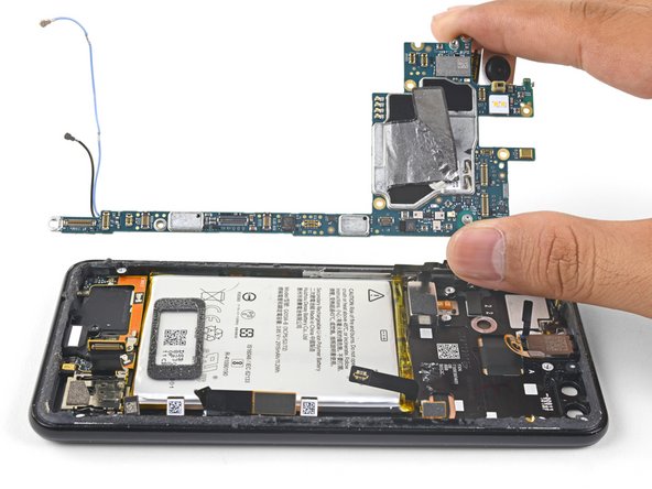
Hebe sorgsam die Hauptplatine am oberen Ende aus dem Rahmen heraus.
-
Entferne die Hauptplatine
-
Möglicherweise lässt sich die Hauptplatine nicht so leicht um das Flachbandkabel zum Ohrhörer positionieren. Du kannst den Ohrhörer-Lautsprecher vorsichtig hochhebeln, die Hauptplatine einbauen und dann den Ohrhörer-Lautsprecher wieder einsetzen.
-
-
-
Erwärme einen iOpener und lege ihn eine Minute lang auf die Unterkante des Displays.
-
Bringe einen Saugheber an der Unterkante des Displays nahe am USB-C Anschluss an.
-
Hebe den Saugheber mit gleichmäßigem und kräftigem Zug an, bis sich ein Spalt bildet.
-
Du kannst auch versuchen, den Zugang an einer langen Kante des Smartphones zu schaffen.
-
Setze ein Plektrum in den Spalt ein.
-
-
-
Schiebe das Plektrum an der Blende entlang und schneide die Klebeverbindung auf.
-
-
-
Erwärme mit dem iOpener die Kanten und durchtrenne den Kleber an allen Kanten mit einem Plektrum.
-
-
-
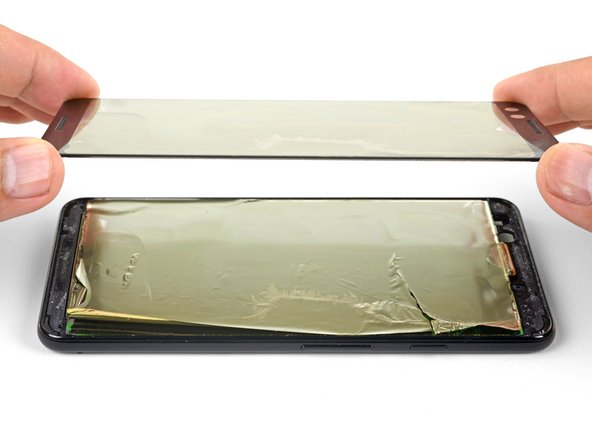
Hebe das Frontglas hoch und entferne es vom Smartphone.
-
-
-
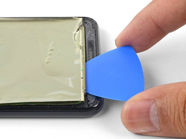
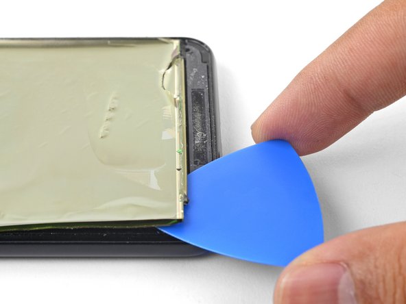
Setze ein Plektrum in die Naht zwischen dem Rahmen des Smartphones und dem verbliebenen Teil des Displays ein.
-
Heble an der Kante entlang, um das Display vom Rahmen abzulösen.
-
-
-
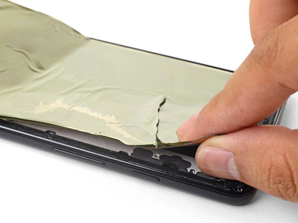
Erwärme und schneide solange am Displayrand, bis du das Display mit den Fingern fassen kannst.
-
Fasse den Displayrand mit den Fingern und ziehe langsam die Überreste des Displays vom Rahmen des Smartphones ab.
-
-
-
Fädle die Kabel des Displays und des Touchscreens aus ihren Ausschnitten heraus. Entferne dann das Display.
-
Entferne alle Klebstoffreste vom Rahmen des Smartphones. Wenn noch Klebstoffreste übrig bleiben, können sie ungleichmäßig auf das Ersatzdisplay drücken und es beschädigen.
-
Bringe vorgestanzte Klebestreifen oder doppelseitiges Klebeband am Rand des Smartphones an.
-
Ziehe alle Schutzfolien von der Rückseite des Ersatzdisplays ab, so dass die Klebeflächen freigelegt werden.
-
Führe sorgfältig die Flachbandkabel des Displays und des Touchscreens durch die Ausschnitte im Rahmen des Smartphones.
-
Lege das Display auf den Rahmen und lasse ein paar Bücher eine Stunde lang darauf liegen, damit das Display gut am Rahmen festklebt.
-


Um dein Gerät wieder zusammenzubauen, folge den Anweisungen in umgekehrter Reihenfolge.
Bitte entsorge deinen Elektroschrott bei einem professionellem Abfallentsorgungsunternehmen.
Deine Reparatur klappte nicht, wie geplant? In unserem Google Pixel 3a Antwortenforum findest du Hilfe bei der Fehlersuche.
Rückgängig: Ich habe diese Anleitung nicht absolviert.
26 weitere Nutzer:innen haben diese Anleitung absolviert.
Besonderer Dank geht an diese Übersetzer:innen:
100%


Diese Übersetzer:innen helfen uns, die Welt zu reparieren! Wie kann ich mithelfen?
Hier starten ›


29 Kommentare
To change only the screen glass… Do you have to disassemble the whole phone or just steps 39 to 42?
Thanks
Hi Adrián,
The OLED is bonded to the screen glass. Unlike LCDs, trying to remove the glass only will most likely destroy the OLED screen.
How to differentiate between a pre-mounted and a non pre-mounted display? I don’t want to order the wrong part, hence the question.
The pre-mounted part will come with the frame, which is the majority of the phone body. The screen is already stuck affixed to the frame, but you would have to transfer everything else onto it. The display only part looks like a thin panel with adhesive on the back. It would look like this part.
When buying a replacement screen do I need to buy it with a frame?
This guide is meant to be used with replacement screens without frames. If you buy a screen with a frame, you will have to transfer many components from your existing frame onto the new one.
My Pixel 3 has a broken screen and also the touchscreen is not working (well, only for half the screen; the top half works just fine, the bottom half does not). Will this guide and replacement parts also fix the touchscreen functionality?
This guide should resolve any issues with the screen, which includes touch functionality.
Also, only because the part in iFixit is out of stock, is this the same part?
Unfortunately, this is not the same part we sell. Like many aftermarket screens for the Pixel, the linked part uses a cheaper LCD panel, while the original Pixel has an OLED. The part may install properly, but the image quality will be different.
Hi again @arthurshi . Following up on my comment from Dec 2. I bought the tools and replacement screen, and performed the repair yesterday. Thanks for the guide!
Everything seemed to go alright… but sadly, the touchscreen functionality remains broken. I installed the new screen. The phone turns on and the screen turns on just fine, but it does not respond to my touch :(
Do you think then that the motherboard’s circuitry for the touchscreen is broken? Or is it more likely that I didn’t connect one of the two screen connectors (I believe the large one is for the display, and the small one for the touch)? Anything I can do to debug/test where the problem is?
Any help is much appreciated. And thanks again for the very useful guide! Even if things don’t end up working, I still learned a lot!
Hey @balldude,
You are right in that one connector is for the screen, and one is for the touch (digitizer). Both must be connected in order for both screen and digitizer to function. The press-fit connectors contain very small contacts. Any small amount of dirt/finger oils on the contacts may cause issues. You can clean them by wiping with lint-free cloth and isopropyl alcohol.
If the screen still won’t respond to touch after that, it may be that the circuitry responsible for the digitizer is broken on the logic board.
Hey, did you try what arthurshi advise and if so did it work. I am also having the same issue and I would hate to buy a new motherboard. Thank in advance.
Hi Jose.
I tried reattaching the connectors a few times and testing it out. I couldn’t get it to work, unfortunately. I ended up buying a new Pixel 4 and sending in the Pixel 3 to Google as a trade-in, for which I received $105.
Hope that helps, and good luck!
Hi to be more in depth the problem I been having is that when I took the screen of my pixel 3 there was a piece of flashing(not sure the proper turn that came off with screen it was glued down to mid frame and the screen is supposed to sit in it. Can you buy this part or do you have to buy a whole new mid frame ? Thank you for your time and all your guides they have been very helpful to me.
Hi S Lee,
Are you speaking of the part shown in step 44? If so, that is part of the display panel. It should be fully removed before you install a replacement screen.
Do NOT follow the author's advice to just “bend up the earpiece speaker flex”. This might work fine enough for board removal, but going backwards, you will likely rip the flex trying to jimmy it back in place. The flex is like plasticated paper ribbon. Just remove the earpiece speaker before you reassemble, and place it in its spot after you put the board back in.
Ps. The plastic insert in step 19 should be given a bit more attention. If you forget to reinstall this plastic insert, the screw that you replace in that spot will instatly ruin your lcd - no matter how gently you screw it in. You'll be left with a green or pink line through your lcd. It seems worth mentioning, as I have seen this before.
Hi Sarah!
Thanks for the suggestions! I will make a note of that and your comment above in the relevant steps.
Followed the guide and was able to install the display in my Pixel 3. Adhesive removal is super frustrating though. But I have a current issue, the rear camera is vibrating like crazy. You could actually hear the camera move around (autofocus) when you open the app. Any ideas?
Hi Levi,
It sounds like the adhesive holding the rear camera is not holding the modules in place. If possible, open the phone, pry the rear cameras up, and install some replacement adhesive.
Hi Arthur, thanks for replying. I feel like I wasn't able to word my problem properly so I made this short video https://youtu.be/cnym7ROK6eU
Seems like an issue in OIS or focusing. Do I need to replace my camera module?
I had major difficulty removing the back panel.
I’m unsure if there was a crack prior to removal of the back panel as the attempt to use the suction and pry tool had catastrophically failed. Huge cracks sprawled as the pry tool was inserted, quite a bit of force was necessary to have the pry tool inserted whilst awkwardly positioning my hands to hold the phone down whilst pulling up on the suction tool. I had used heat tools to ease the adhesive behind the panel but may have lost patience as the heat bags provided does not seem to have the same effect as a heat gun would. That being said, the heat bags, while they heat up I’m unsure if they heat up to the critical temperature of the adhesive for it to weaken.
further instruction for the temperature of the bags would help; what is the max temperature I can warm the bag up before it fails (explodes in the microwave) while meeting minimum temperature required to ease the adhesive. currently it said to warm it up for 30sec, 1 every 10 mins, doesn’t cut it.
as the guide said, “The remaining part of the screen is affixed to the phone frame”. why we need to remove the motherboard?
You unfortunately can't release/reconnect the display flex cable and the digitizer cable without removing the motherboard. There isn't enough of a gap to thread the cable through the side.
Need a big update. I order a new screen and it's not only the screen but the whole case. So, I have to transfer all the components to the new case. It is not explained here.
Just pay close attention when you take it apart.......... take pictures.
keep screws in order so they go back in the same place...
and im sure there are videos on youtube showing screen replacement in-frame
Sorry about that! We accidentally linked that part to this guide. We are in the process of writing a guide specifically for the screen and frame assembly replacement part.
Older devices may require 2 or more minutes with a very hot iOpener. Also note, the photo shows the opener on the FRONT of the phone. The heat needs to be applied to the back of the device!
Rick Johnson - Antwort
I just realized that I was trying to pry apart the front of my Pixel 3… and have separated the class from the display. ??♂️ Even though the rest of the directions show the back, it would be nice for the first picture to also show the back, just to be safe.
JR Raith -
Agreed, I’ve done exactly the same and completely broken my display. I probably should’ve paid more attention to the initial steps before diving in but the step could do with a new picture for sure.
Daniel Fryer -
Thanks for the comments! I’ll add a note in the step warning people to make sure to pry the back cover, not the screen.
Arthur Shi -
I prefer my favorite opening method with something like this. Dental floss. So thin it can slide in the gap. A little sawing to get it far enough past the edge to lift and get the first pick in.
John Hoffstetter - Antwort
I found another wonderful tool. I used something like medicine packaging which is aluminum foil with plastic. It’s thin and strong enough!
Christie Lin - Antwort
I also went for the hairdryer, dental floss, and then the provided picks and this worked. Not easy to get that initial seal broken but once that's done the rest is pretty easy.
James - Antwort
I needed 20 nerve wracking minutes with a hairdryer
Amy schneider - Antwort
My battery had bulged and opened the case for me!
Warmed it up a bit with hairdryer
Floss helped also.
David Lincer - Antwort
I found I wasn't able to get the edges hot enough. I ended up using my heat gun (for shrink tubing) instead.
Kurt Nowak - Antwort