Diese Version enthält möglicherweise inkorrekte Änderungen. Wechsle zur letzten geprüften Version.
Was du brauchst
-
Dieser Schritt ist noch nicht übersetzt. Hilf mit, ihn zu übersetzen!
-
Turn laptop upside down.
-
Flip the lock switch to the unlocked setting.
-
-
Dieser Schritt ist noch nicht übersetzt. Hilf mit, ihn zu übersetzen!
-
Flip the release switch.
-
Once the flip is switched, the battery should pop out.
-
-
Dieser Schritt ist noch nicht übersetzt. Hilf mit, ihn zu übersetzen!
-
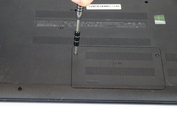
Remove the two Phillips #1 screws from the RAM panel.
-
-
Dieser Schritt ist noch nicht übersetzt. Hilf mit, ihn zu übersetzen!
-
Use the plastic opening tool to pop the panel off.
-
-
Dieser Schritt ist noch nicht übersetzt. Hilf mit, ihn zu übersetzen!
-
Release the tabs on each side of the chip by simultaneously pushing each tab away from the RAM.
-
-
Dieser Schritt ist noch nicht übersetzt. Hilf mit, ihn zu übersetzen!
-
Remove the RAM chip from the laptop.
-
-
Dieser Schritt ist noch nicht übersetzt. Hilf mit, ihn zu übersetzen!
-
Remove the sixteen 7mm Phillips #1 screws from the bottom panel.
-
-
Dieser Schritt ist noch nicht übersetzt. Hilf mit, ihn zu übersetzen!
-
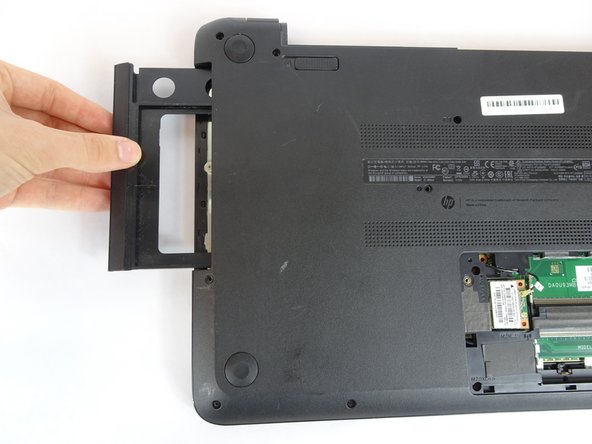
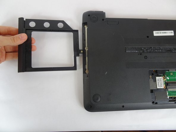
Pull the disk drive out of the laptop.
-
-
-
Dieser Schritt ist noch nicht übersetzt. Hilf mit, ihn zu übersetzen!
-
Remove the three 2mm Phillips #00 screws found underneath the disk drive.
-
-
Dieser Schritt ist noch nicht übersetzt. Hilf mit, ihn zu übersetzen!
-
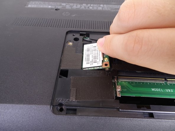
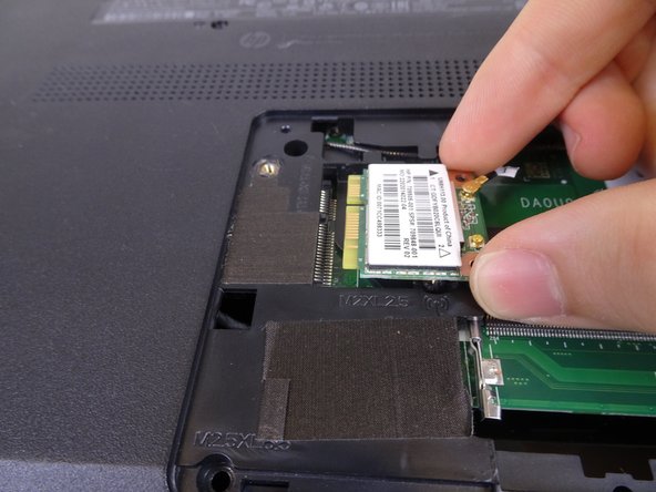
Remove the single 4mm Phillips #1 screw from the Wi-Fi card.
-
Pull the Wi-Fi card out of the motherboard.
-
-
Dieser Schritt ist noch nicht übersetzt. Hilf mit, ihn zu übersetzen!
-
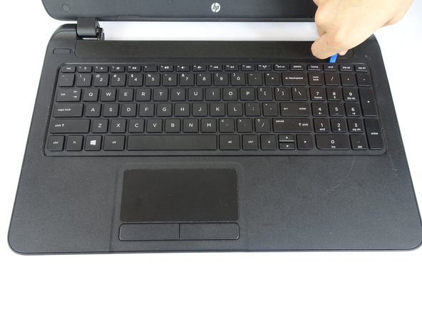
Open the laptop.
-
Use a plastic opening tool to pop out the keyboard by starting at the top and working your way around the perimeter.
-
-
Dieser Schritt ist noch nicht übersetzt. Hilf mit, ihn zu übersetzen!
-
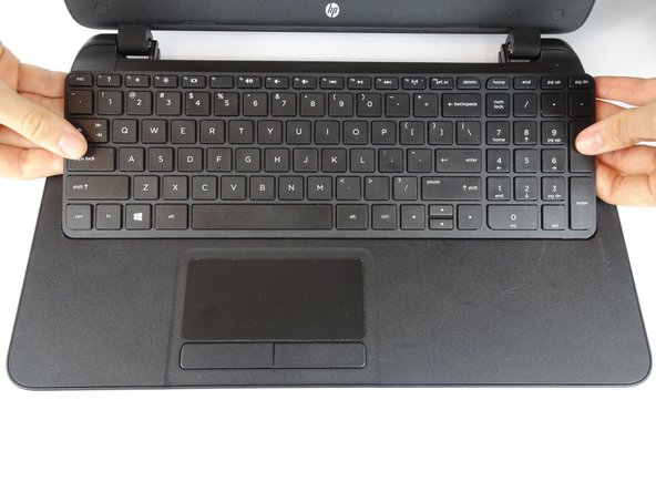
Open the screen up until it lays flat and rotate the laptop until the screen is closest to you.
-
Lift the keyboard from the laptop.
-
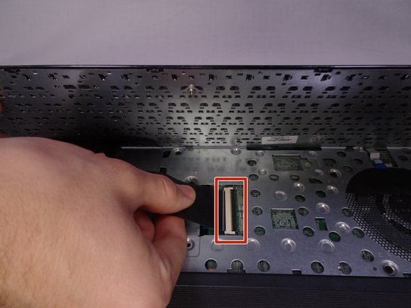
Use a spudger to lift up the black latch on the ZIF connector and remove the ribbon cable.
-
-
Dieser Schritt ist noch nicht übersetzt. Hilf mit, ihn zu übersetzen!
-
Remove the five 7mm Phillips #1 screws found underneath the keyboard.
-
-
Dieser Schritt ist noch nicht übersetzt. Hilf mit, ihn zu übersetzen!
-
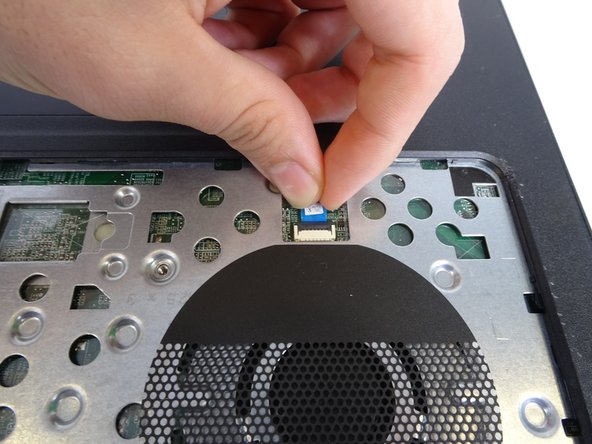
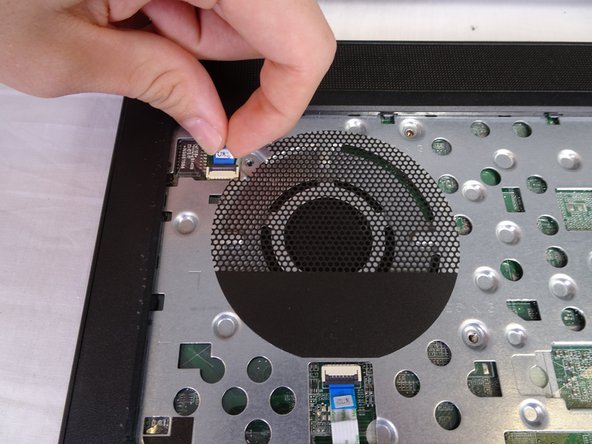
Use a spudger to lift the black tabs on the ZIF connectors.
-
Remove the ribbon cables from the ZIF connectors.
-
-
Dieser Schritt ist noch nicht übersetzt. Hilf mit, ihn zu übersetzen!
-
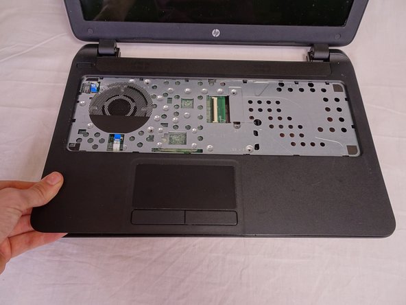
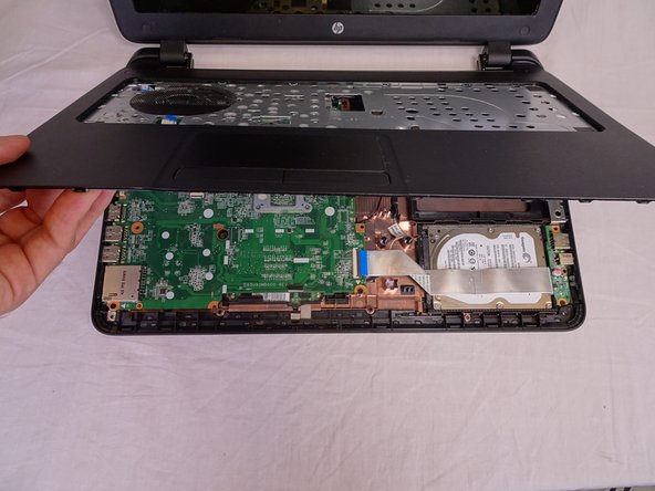
Use a plastic opening tool to pop the palm rest off of the laptop.
-
Lift and remove the palm rest.
-
-
Dieser Schritt ist noch nicht übersetzt. Hilf mit, ihn zu übersetzen!
-
Use a spudger to lift up the black latch on the ZIF connector.
-
Remove the USB/AUX port ribbon cable from the ZIF connector on the motherboard.
-
-
Dieser Schritt ist noch nicht übersetzt. Hilf mit, ihn zu übersetzen!
-
Remove the single 7mm Phillips #1 screw from the USB/AUX board.
-
Remove the USB/AUX board from the laptop.
-
-
Dieser Schritt ist noch nicht übersetzt. Hilf mit, ihn zu übersetzen!
-
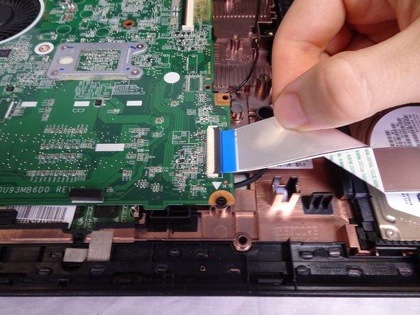
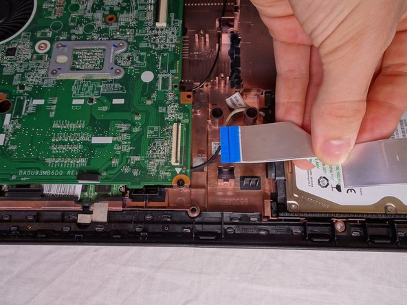
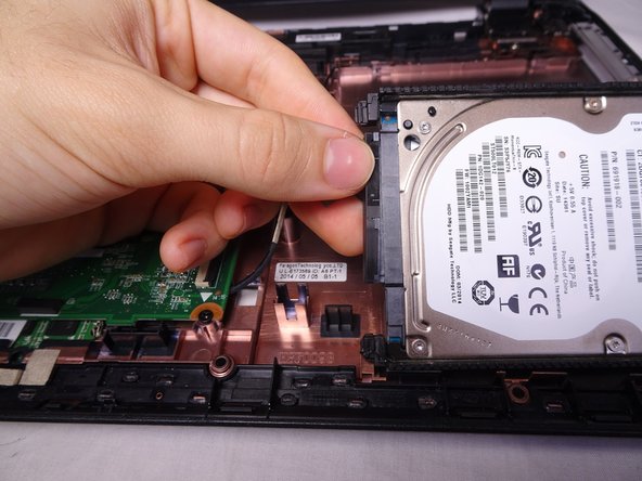
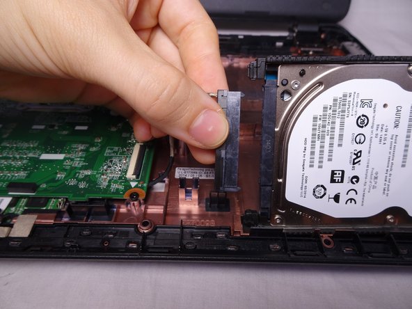
Lift the Hard Drive from the laptop.
-
Disconnect the hard drive from the motherboard.
-
-
Dieser Schritt ist noch nicht übersetzt. Hilf mit, ihn zu übersetzen!
-
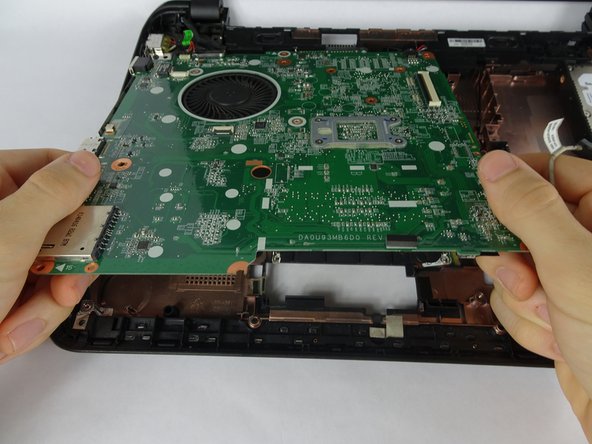
Remove the four 4mm Phillips #1 screws from the motherboard.
-
Lift the motherboard up from the computer.
-
-
Dieser Schritt ist noch nicht übersetzt. Hilf mit, ihn zu übersetzen!
-
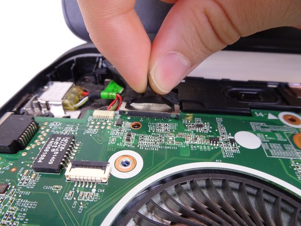
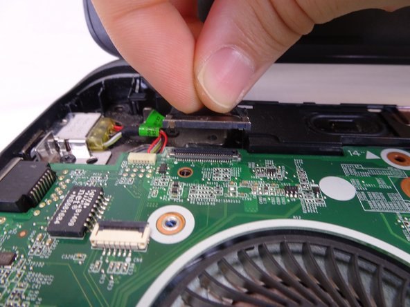
Remove the display connection wire. Lift the connection straight up from the motherboard.
-
-
Dieser Schritt ist noch nicht übersetzt. Hilf mit, ihn zu übersetzen!
-
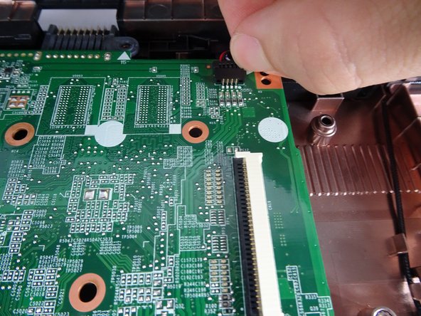
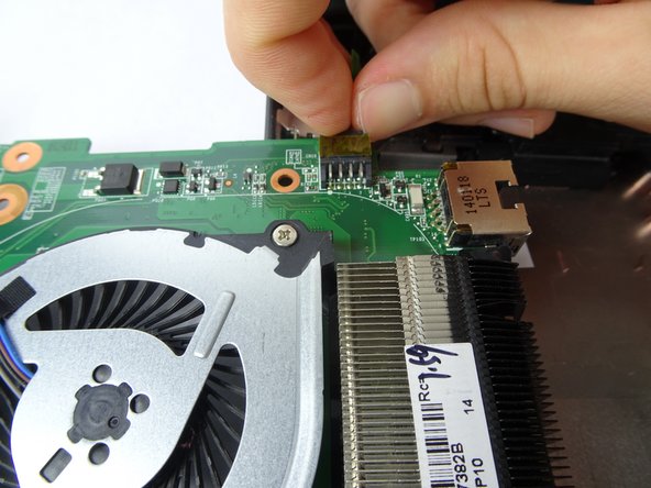
Flip the motherboard over.
-
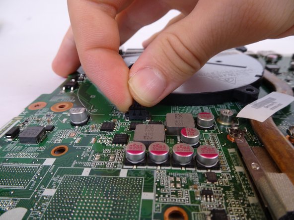
Disconnect the charging port wire from the motherboard.
-
-
Dieser Schritt ist noch nicht übersetzt. Hilf mit, ihn zu übersetzen!
-
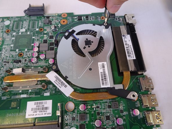
Use the PH1 Screwdriver to remove the two screws (7 mm) which hold the fan in place.
-
-
Dieser Schritt ist noch nicht übersetzt. Hilf mit, ihn zu übersetzen!
-
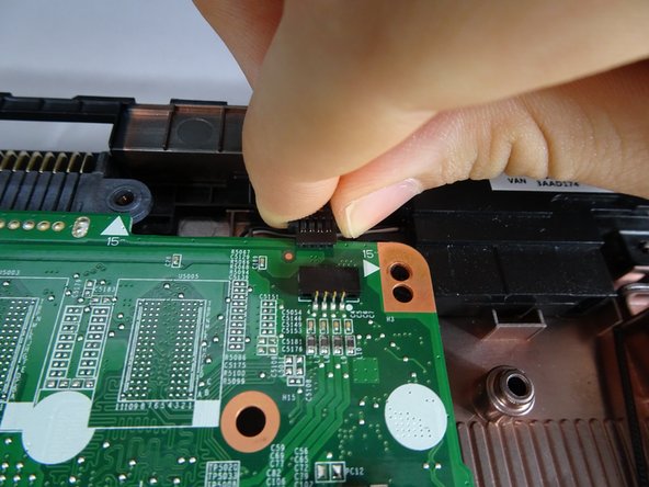
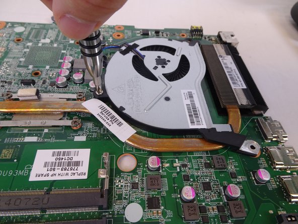
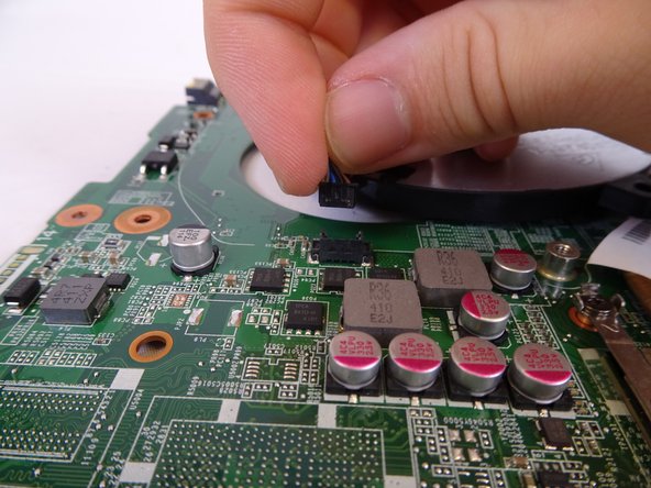
The fan will now only be connected via its connection wire.
-
Unplug the connection wire.
-


Rückgängig: Ich habe diese Anleitung nicht absolviert.
Ein:e weitere:r Nutzer:in hat diese Anleitung absolviert.
Team

USF Tampa, Team S2-G2, Nance Spring 2018 Mitglied von USF Tampa, Team S2-G2, Nance Spring 2018
USFT-NANCE-S18S2G2
4 Mitglieder
5 Anleitungen geschrieben