Diese Version enthält möglicherweise inkorrekte Änderungen. Wechsle zur letzten geprüften Version.
Was du brauchst
-
Dieser Schritt ist noch nicht übersetzt. Hilf mit, ihn zu übersetzen!
-
Flip the laptop upside down so that the lid lies flat on the table.
-
Remove the nine 6mm Phillips #00 screws that line the border.
-
-
Dieser Schritt ist noch nicht übersetzt. Hilf mit, ihn zu übersetzen!
-
Remove the two rubber feet closest to the hinge using tweezers.
-
Remove the two 6mm Phillips #00 screws revealed under these rubber feet.
-
-
Dieser Schritt ist noch nicht übersetzt. Hilf mit, ihn zu übersetzen!
-
Flip the laptop so it is in the upright position.
-
Open the lid.
-
Unsnap the keyboard mount along the border of the laptop using a plastic opening tool.
-
-
Dieser Schritt ist noch nicht übersetzt. Hilf mit, ihn zu übersetzen!
-
Tilt the keyboard mount up.
-
Use a spudger to flip up the two ZIF connector retaining flaps for the ribbon cables that connect the keyboard mount to the motherboard.
-
Gently remove both ribbon cables.
-
-
Dieser Schritt ist noch nicht übersetzt. Hilf mit, ihn zu übersetzen!
-
Lift the keyboard mount out of the laptop.
-
-
-
Dieser Schritt ist noch nicht übersetzt. Hilf mit, ihn zu übersetzen!
-
Gently pull the battery’s rainbow-colored, bundled cable out of its socket.
-
-
Dieser Schritt ist noch nicht übersetzt. Hilf mit, ihn zu übersetzen!
-
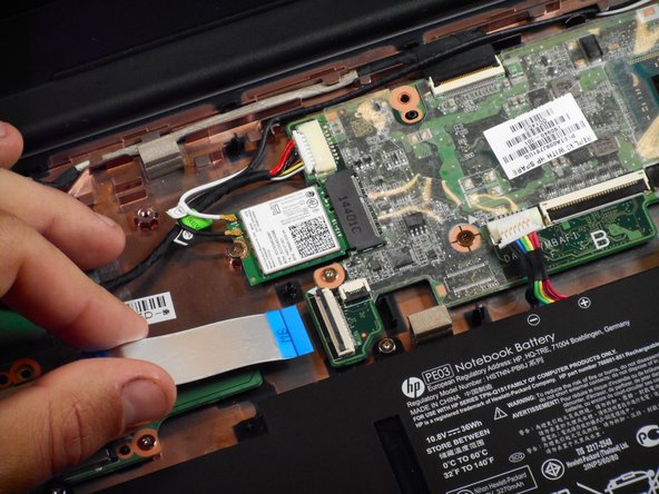
Use a spudger to lift the small ZIF retaining flap for the ribbon cable that connects the SD card reader to the motherboard.
-
Gently pull the cable out of its socket.
-
-
Dieser Schritt ist noch nicht übersetzt. Hilf mit, ihn zu übersetzen!
-
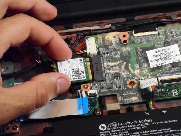
Remove the 2 mm Phillips #00 screw that holds the Wi-Fi module in place.
-
Slide the Wi-Fi module out of the motherboard.
-
-
Dieser Schritt ist noch nicht übersetzt. Hilf mit, ihn zu übersetzen!
-
Gently pull the bundled cable that connects the charging port to the motherboard out of its connector on the motherboard.
-
-
Dieser Schritt ist noch nicht übersetzt. Hilf mit, ihn zu übersetzen!
-
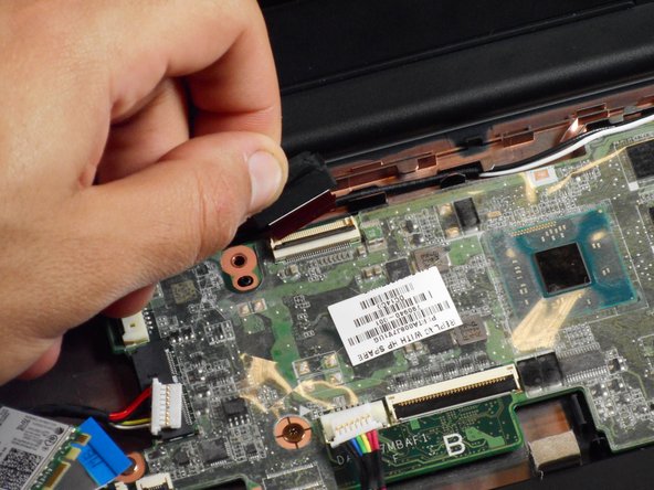
Use a spudger to lift the small ZIF retaining flip for the ribbon cable that connects the display to the motherboard.
-
Gently pull the cable out of its socket.
-
-
Dieser Schritt ist noch nicht übersetzt. Hilf mit, ihn zu übersetzen!
-
Use a spudger to remove the slide-out connector from its socket.
-
-
Dieser Schritt ist noch nicht übersetzt. Hilf mit, ihn zu übersetzen!
-
Remove the center-right Phillips #1 3mm screw.
-
-
Dieser Schritt ist noch nicht übersetzt. Hilf mit, ihn zu übersetzen!
-
Remove the center-left Phillips #00 4mm screw.
-
-
Dieser Schritt ist noch nicht übersetzt. Hilf mit, ihn zu übersetzen!
-
Remove the four perimeter Phillips #00 6mm screws.
-
-
Dieser Schritt ist noch nicht übersetzt. Hilf mit, ihn zu übersetzen!
-
Gently slide the motherboard to the left and away from the external ports on the right and then pull it up and out of the laptop.
-


Rückgängig: Ich habe diese Anleitung nicht absolviert.
Ein:e weitere:r Nutzer:in hat diese Anleitung absolviert.

Team

Cal Poly, Team S23-G3, Livingston Spring 2017 Mitglied von Cal Poly, Team S23-G3, Livingston Spring 2017
CPSU-LIVINGSTON-S17S23G3
4 Mitglieder
12 Anleitungen geschrieben