Diese Version enthält möglicherweise inkorrekte Änderungen. Wechsle zur letzten geprüften Version.
Was du brauchst
-
-
Benutze ein Öffnungswerkzeug aus Kunststoff und deine Hände, um die Unterseite zu entfernen.
-
-
-
Entferne die sechs 6 mm #0 Kreuzschlitzschrauben, mit denen der Akku befestigt ist.
-
-
Dieser Schritt ist noch nicht übersetzt. Hilf mit, ihn zu übersetzen!
-
Remove two 3mm Phillips #00 screws from the fan.
-
-
Dieser Schritt ist noch nicht übersetzt. Hilf mit, ihn zu übersetzen!
-
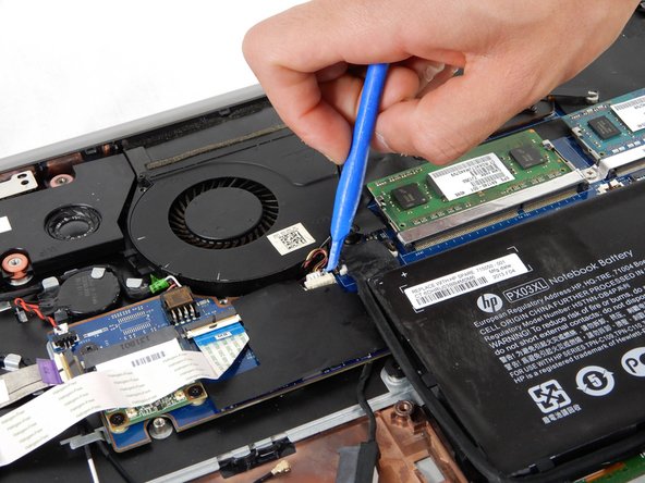
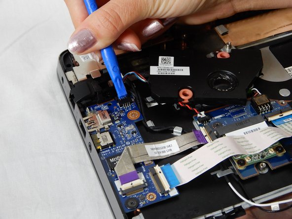
Disconnect the fan cable by pulling it out of the motherboard socket.
-
-
-
Dieser Schritt ist noch nicht übersetzt. Hilf mit, ihn zu übersetzen!
-
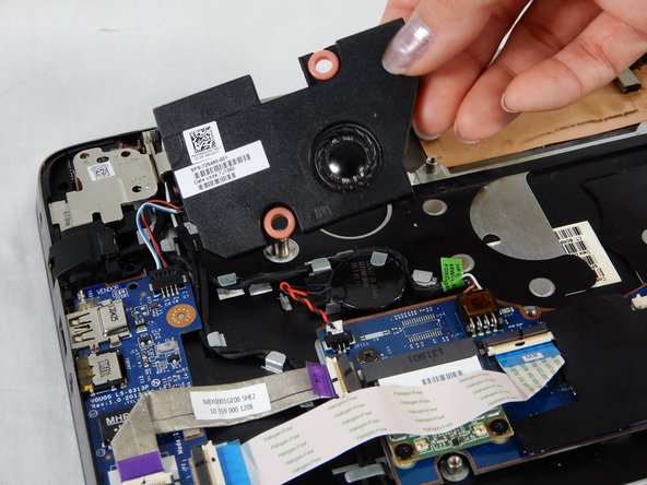
Lift the fan upwards to remove it from the computer.
-
-
Dieser Schritt ist noch nicht übersetzt. Hilf mit, ihn zu übersetzen!
-
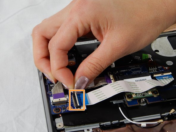
Flip up the black tab on the ZIF connector and pull the blue and white flex cable connecting the touchpad to the motherboard.
-
-
Dieser Schritt ist noch nicht übersetzt. Hilf mit, ihn zu übersetzen!
-
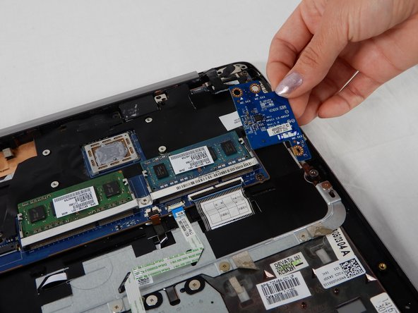
Remove three 3mm Phillips #00 screws from the SD card board.
-
Remove the SD card board.
-
-
Dieser Schritt ist noch nicht übersetzt. Hilf mit, ihn zu übersetzen!
-
In order to remove the RAM, pull each silver clip (one at a time) away from the RAM.
-
The RAM chip should pop up. Gently remove the RAM from the motherboard.
-
-
Dieser Schritt ist noch nicht übersetzt. Hilf mit, ihn zu übersetzen!
-
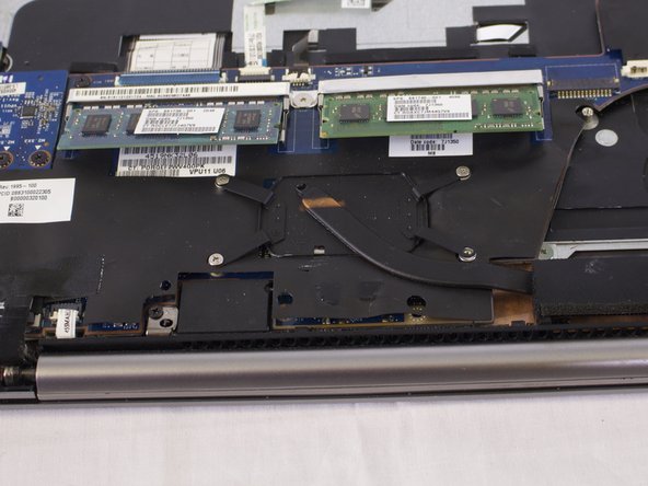
Remove four 3mm Phillips #00 screws from the heatsink.
-
Lift the heat sink out from the device and set it aside.
-
-
Dieser Schritt ist noch nicht übersetzt. Hilf mit, ihn zu übersetzen!
-
Remove the black and white antenna wires from the Wi-Fi card.
-
-
Dieser Schritt ist noch nicht übersetzt. Hilf mit, ihn zu übersetzen!
-
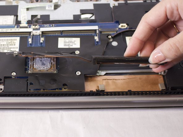
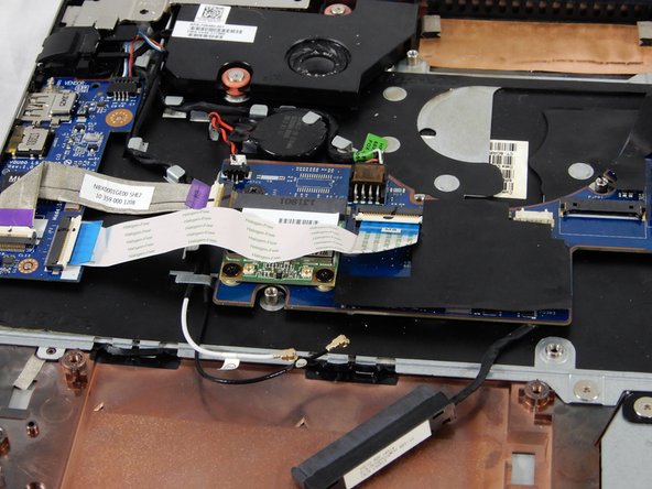
Remove the two 3mm Phillips #00 screws that secure the speaker to the device.
-
Remove the four 4mm Phillips #00 screws from the bracket.
-
Locate the speaker cable connecting the speaker to the audio board. Gently tug on this cable to dislodge. Set the speaker aside.
-
-
Dieser Schritt ist noch nicht übersetzt. Hilf mit, ihn zu übersetzen!
-
Remove the two 3mm Phillips #00 screws that secure the RJ-45 module.
-
Lift the white tab on the ZIF connector and pull the ribbon cable out.
-
-
Dieser Schritt ist noch nicht übersetzt. Hilf mit, ihn zu übersetzen!
-
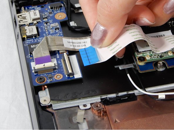
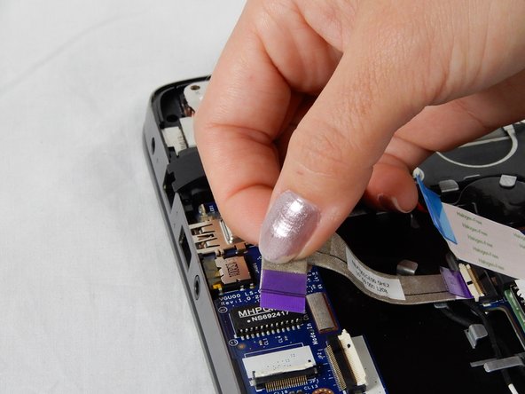
Remove the 3mm Phillips #00 screw connecting the chip to the housing.
-
Lift up silver bracket.
-
Lift up the white flap on the ZIF connector and remove the purple ribbon cable.
-
-
Dieser Schritt ist noch nicht übersetzt. Hilf mit, ihn zu übersetzen!
-
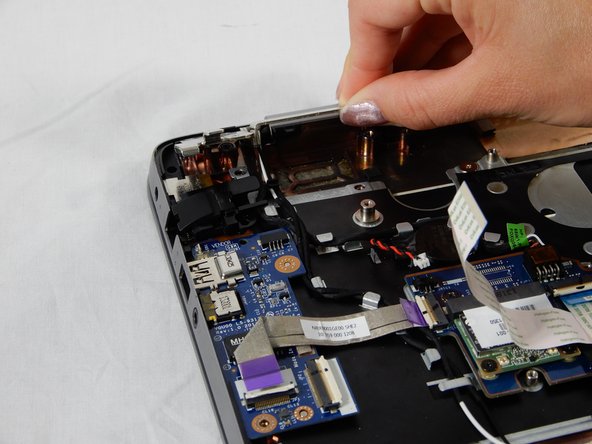
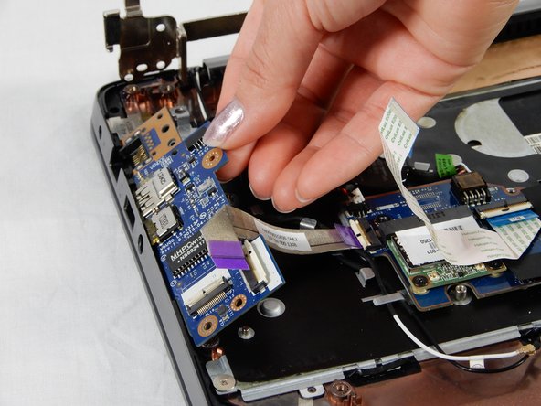
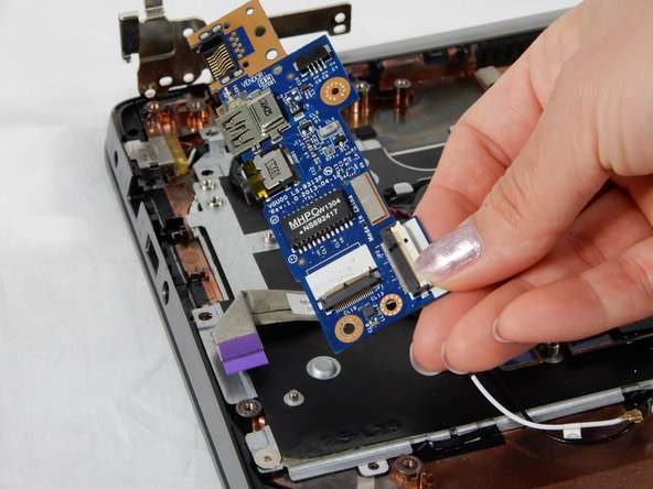
Remove the cover for the RM-45 port.
-
Gently lift and remove the chip from its housing.
-
-
Dieser Schritt ist noch nicht übersetzt. Hilf mit, ihn zu übersetzen!
-
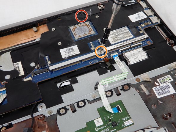
Remove the 4mm Phillips #00 screws.
-
Remove the silver 3mm Phillips 3 mm screw.
-
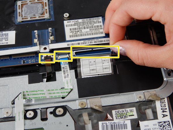
Lift all three black flaps in the ZIF connectors and remove the attached ribbon cables.
-
-
Dieser Schritt ist noch nicht übersetzt. Hilf mit, ihn zu übersetzen!
-
Use your hand and gently remove the connector to the back up battery for the motherboard.
-
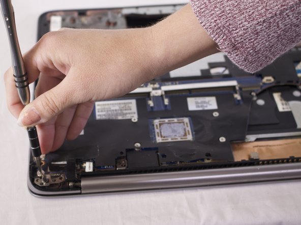
Remove the four 4mm Phillips #00 screws from the motherboard.
-
Lift the board at an angle and pull outwards to dislodge it from the device.
-
-
Dieser Schritt ist noch nicht übersetzt. Hilf mit, ihn zu übersetzen!
-
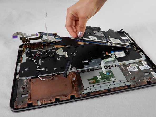
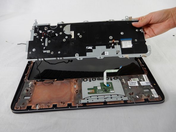
Remove the thirteen silver 3mm Phillips #00 screws that secure the keyboard to the frame.
-
Lift up the keyboard from the bracket and pull outwards to remove the keyboard from the device.
-


Rückgängig: Ich habe diese Anleitung nicht absolviert.
2 weitere Nutzer:innen haben diese Anleitung absolviert.
Team

USF Tampa, Team S1-G4, Nance Spring 2018 Mitglied von USF Tampa, Team S1-G4, Nance Spring 2018
USFT-NANCE-S18S1G4
4 Mitglieder
15 Anleitungen geschrieben