Diese Übersetzung enthält möglicherweise noch nicht die neuesten Änderungen der Original-Anleitung. Hilf mit, die Übersetzung zu aktualisieren oder sieh dir die Original-Anleitung an.
Was du brauchst
-
-
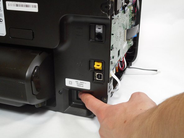
Turn the printer so the back is facing you.
-
Put the printer in a vertical position by lifting its right side.
-
-
Dieser Schritt ist noch nicht übersetzt. Hilf mit, ihn zu übersetzen!
-
Remove the two 12mm-T10 Torx screws on the top edge of the printer.
-
-
Dieser Schritt ist noch nicht übersetzt. Hilf mit, ihn zu übersetzen!
-
Rotate the printer clockwise so the bottom of the printer is facing you.
-
-
Dieser Schritt ist noch nicht übersetzt. Hilf mit, ihn zu übersetzen!
-
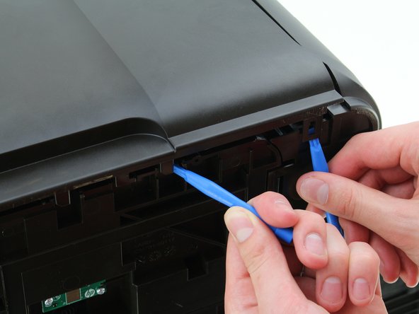
Insert the plastic opening tool underneath the slot on the right that aligns with the edge of the back panel.
-
Insert a second plastic opening tool in the notch lining up with the crease in the back panel.
-
-
-
Dieser Schritt ist noch nicht übersetzt. Hilf mit, ihn zu übersetzen!
-
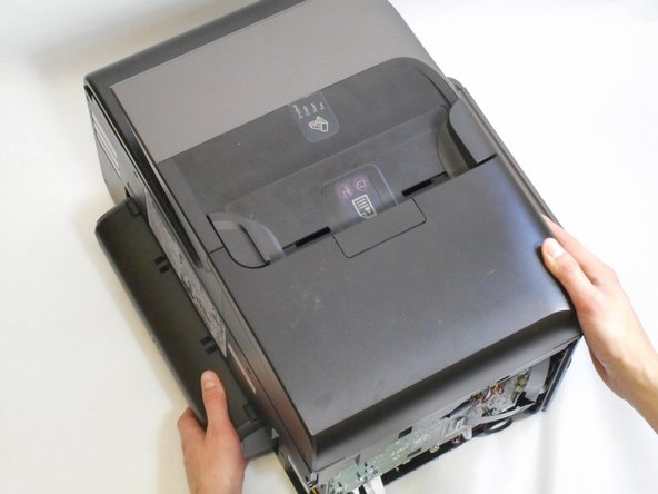
Remove the side panel from the printer by lifting upwards toward you.
-
-
Dieser Schritt ist noch nicht übersetzt. Hilf mit, ihn zu übersetzen!
-
Rotate the printer to its standard position.
-
-
Dieser Schritt ist noch nicht übersetzt. Hilf mit, ihn zu übersetzen!
-
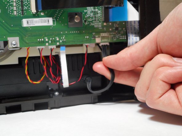
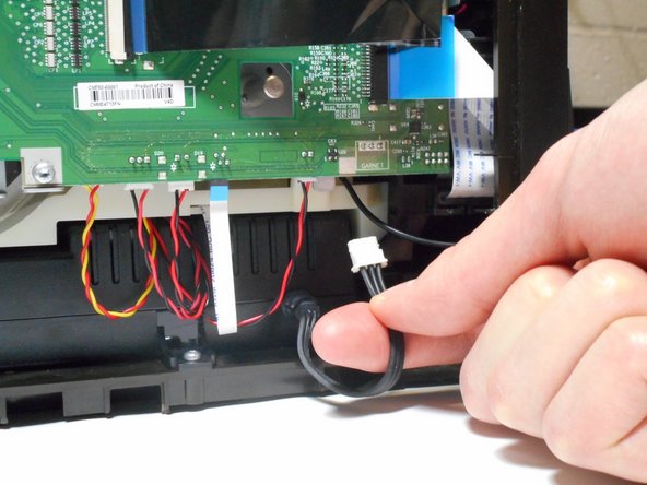
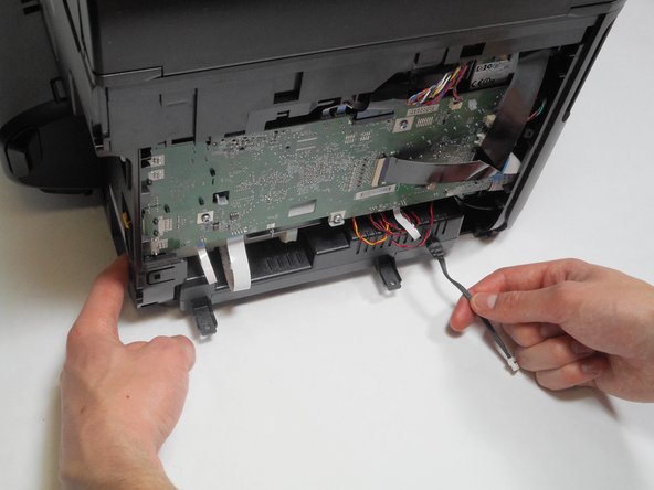
Unplug the black wire with the white cap connecting the power supply to the motherboard.
-
-
Dieser Schritt ist noch nicht übersetzt. Hilf mit, ihn zu übersetzen!
-
Remove the two 12mm-T10 Torx screws from the base of the power supply mount.
-
-
Dieser Schritt ist noch nicht übersetzt. Hilf mit, ihn zu übersetzen!
-
Place your left hand on the left side of the power supply through the opening in the side of the printer.
-
-
Dieser Schritt ist noch nicht übersetzt. Hilf mit, ihn zu übersetzen!
-
Grab the base of the cable on the right side of the power supply with your right hand.
-
Remove the power supply by pulling your right hand toward you and pushing your left fingers toward you.
-


Rückgängig: Ich habe diese Anleitung nicht absolviert.
9 weitere Nutzer:innen haben diese Anleitung absolviert.
Besonderer Dank geht an diese Übersetzer:innen:
7%

BOSE Box hilft uns, die Welt in Ordnung zu bringen! Wie kann ich mithelfen?
Hier starten ›
Team

Cal Poly, Team S16-G4, Livingston Spring 2018 Mitglied von Cal Poly, Team S16-G4, Livingston Spring 2018
CPSU-LIVINGSTON-S18S16G4
4 Mitglieder
10 Anleitungen geschrieben
3 Kommentare
I have used this guide to replace the power supply for my Officejet 8715. The only difference is a third screw that needs to be removed to take the cover off.
This is an easy repair.
The real challenge is to find the right replacement part. The power supply is used in various models.
The OEM Number of the power supply is E3E01-60132
I have paid for this spare part less than 30€. Worthwhile as a new printer costs around 300€.
Does the 8600 P/S fit on the 8620? If not, what is part nr for 8620?
Un peu galère dommage que j'ai pas trouvé se blog avant car a par les visse chiant à défaire c'est bien expliquer après essai du fusibles en porcelaine jus arrive et rien derrière donc merci