Diese Version enthält möglicherweise inkorrekte Änderungen. Wechsle zur letzten geprüften Version.
Was du brauchst
-
Dieser Schritt ist noch nicht übersetzt. Hilf mit, ihn zu übersetzen!
-
Lay the computer face-down on a flat surface. Orient the computer to match the image.
-
Locate the battery release switch, as indicated in the image by the red rectangle. Slide the switch from right to left, and remove the battery.
-
-
Dieser Schritt ist noch nicht übersetzt. Hilf mit, ihn zu übersetzen!
-
Remove the two 5mm Phillips screws on the right side of the RAM cover.
-
Lift the right side of the RAM cover, and remove it.
-
-
Dieser Schritt ist noch nicht übersetzt. Hilf mit, ihn zu übersetzen!
-
Disconnect the antenna leads from the wifi card by lifting the gold ends of the wires off the prongs on the wifi card.
-
The white wire connects to the AUX terminal.
-
The black wire connects to the MAIN terminal.
-
-
Dieser Schritt ist noch nicht übersetzt. Hilf mit, ihn zu übersetzen!
-
Remove the two 6.0mm Phillips screws from the wifi card.
-
Remove the wifi card.
-
-
Dieser Schritt ist noch nicht übersetzt. Hilf mit, ihn zu übersetzen!
-
Locate the hard drive cover. Note that in this image, the RAM cover is still in place.
-
-
Dieser Schritt ist noch nicht übersetzt. Hilf mit, ihn zu übersetzen!
-
Remove the two screws securing the hard drive cover.
-
-
Dieser Schritt ist noch nicht übersetzt. Hilf mit, ihn zu übersetzen!
-
Remove the two 5.0mm screws securing the hard drive bracket.
-
-
Dieser Schritt ist noch nicht übersetzt. Hilf mit, ihn zu übersetzen!
-
Slide the hard drive to the right until the edge of the hard drive is flush with the computer frame.
-
Lift the hard drive out of the hard drive bay, left side first.
-
-
-
Dieser Schritt ist noch nicht übersetzt. Hilf mit, ihn zu übersetzen!
-
Remove the 11.0mm screw securing the optical drive to the computer.
-
-
Dieser Schritt ist noch nicht übersetzt. Hilf mit, ihn zu übersetzen!
-
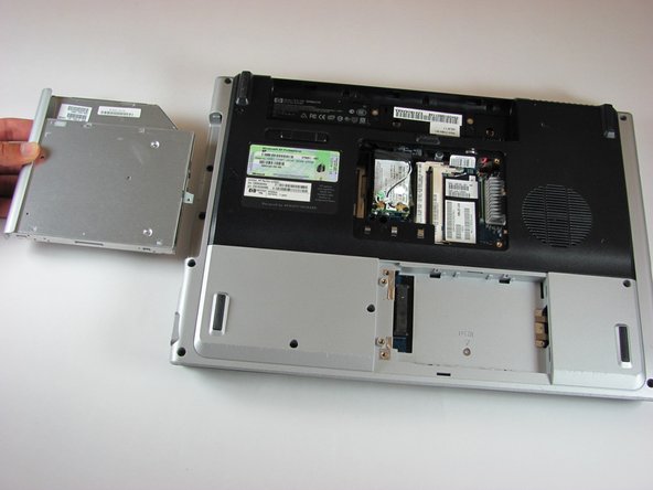
Locate the optical drive. The optical drive is located on the left side of the RAM bay.
-
Press the exposed edge of the optical drive gently with the spudger until the drive releases from the computer frame.
-
Pull the optical drive completely out of the computer frame.
-
-
Dieser Schritt ist noch nicht übersetzt. Hilf mit, ihn zu übersetzen!
-
Remove the two 11.0mm screws at the corners on either side of the battery compartment.
-
Remove the three 6.0mm screws.
-
Remove the two 5.0mm screws.
-
Remove the 6.0mm screw in the middle of the battery compartment.
-
-
Dieser Schritt ist noch nicht übersetzt. Hilf mit, ihn zu übersetzen!
-
Turn the computer over and open the screen. This provides access to the screen hinges.
-
The keyboard switch cover is attached to the computer with a series of snaps. With a flathead screwdriver, pry up the switch cover until it pops free.
-
-
Dieser Schritt ist noch nicht übersetzt. Hilf mit, ihn zu übersetzen!
-
Be careful not to bend the keyboard switch cover too far when removing it.
-
-
Dieser Schritt ist noch nicht übersetzt. Hilf mit, ihn zu übersetzen!
-
Next, remove the keyboard. Push on the keyboard frame above the function keys and slide the keyboard toward the screen.
-
-
Dieser Schritt ist noch nicht übersetzt. Hilf mit, ihn zu übersetzen!
-
Carefully lift the trackpad-side edge of the keyboard to reveal the LED and keyboard cable connectors.
-
Detach the cable connectors from the computer by gripping each cable connector close to the computer contact point and pulling up gently.
-
-
Dieser Schritt ist noch nicht übersetzt. Hilf mit, ihn zu übersetzen!
-
Lay the keyboard face down.
-
Remove the four 3.00mm screws that attach the keyboard to the keyboard frame.
-
-
Dieser Schritt ist noch nicht übersetzt. Hilf mit, ihn zu übersetzen!
-
Lift the keyboard off the keyboard frame.
-
-
Dieser Schritt ist noch nicht übersetzt. Hilf mit, ihn zu übersetzen!
-
Remove the two 3.0mm screws on the side of the laptop shown.
-
Remove the one 5.0mm screw in the hard drive compartment.
-
-
Dieser Schritt ist noch nicht übersetzt. Hilf mit, ihn zu übersetzen!
-
Remove the eight 10mm screws securing the top cover to the laptop.
-
-
Dieser Schritt ist noch nicht übersetzt. Hilf mit, ihn zu übersetzen!
-
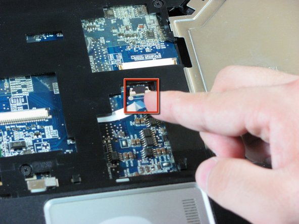
Flip the computer over and disconnect the Touchpad Cable.
-
-
Dieser Schritt ist noch nicht übersetzt. Hilf mit, ihn zu übersetzen!
-
Remove the silver 5.0mm screws Located in the silver area of the top cover
-
Remove the seven 10.0mm screws located on the top cover.
-
-
Dieser Schritt ist noch nicht übersetzt. Hilf mit, ihn zu übersetzen!
-
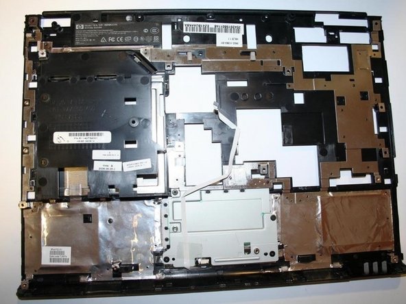
Lift off the top cover and remove it. Lift off from the back.
-
-
Dieser Schritt ist noch nicht übersetzt. Hilf mit, ihn zu übersetzen!
-
Congratulations! You're ready to install the new assembly and reassemble your laptop!
-
-
Dieser Schritt ist noch nicht übersetzt. Hilf mit, ihn zu übersetzen!
-
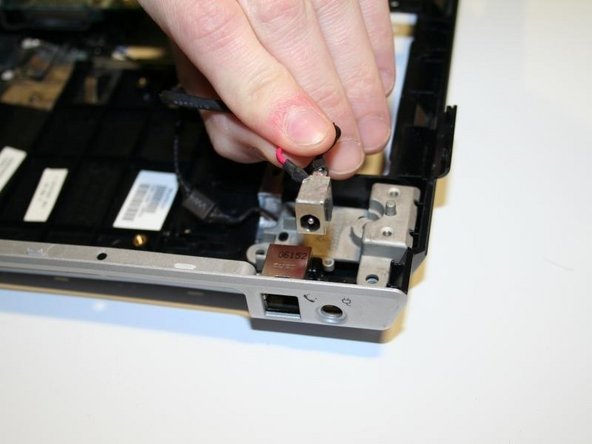
Locate the Power Supply Port
-
Lift the port up to remove it from its seated position
-


Team

UMass Dartmouth, Team 4-5, Calaway Spring 2014 Mitglied von UMass Dartmouth, Team 4-5, Calaway Spring 2014
UMASSD-CALAWAY-S14S4G5
4 Mitglieder
3 Anleitungen geschrieben