Diese Version enthält möglicherweise inkorrekte Änderungen. Wechsle zur letzten geprüften Version.
Was du brauchst
-
Dieser Schritt ist noch nicht übersetzt. Hilf mit, ihn zu übersetzen!
-
Locate the battery on the bottom side of the laptop.
-
Slide the release switch and the battery will pop out.
-
Remove the battery
-
-
Dieser Schritt ist noch nicht übersetzt. Hilf mit, ihn zu übersetzen!
-
Using a Philips #1 Loosen the three 7mm captive screws that secure the memory module compartment cover to the computer.
-
Lift the rear edge of the cover, swing it up and to the front, and remove the cover.
-
-
Dieser Schritt ist noch nicht übersetzt. Hilf mit, ihn zu übersetzen!
-
Loosen the two 6mm captive screws that secure the hard drive port bezel cover to the computer, using a Philips #1.
-
Lift the right side of the hard drive port bezel cover, swing it up and to the left, and remove the cover.
-
-
Dieser Schritt ist noch nicht übersetzt. Hilf mit, ihn zu übersetzen!
-
Use the Mylar tab to lift the hard drive up, and then slide it to the left to release it from the hard drive bay.
-
-
Dieser Schritt ist noch nicht übersetzt. Hilf mit, ihn zu übersetzen!
-
Disconnect the hard drive cable from the system board.
-
Remove the hard drive from the hard drive bay and set it aside.
-
-
Dieser Schritt ist noch nicht übersetzt. Hilf mit, ihn zu übersetzen!
-
With laptop upside down locate the three sets of screws that fasten the keyboard and switch cover.
-
Two Phillips 7mm screws that secure the switch cover to the computer.
-
Four Phillips 4.0mm screws that secure the switch cover to the computer. (these are inside the battery bay)
-
Four Philips 7mm screws that secure the keyboard to the computer.
-
Remove all ten screws.
-
-
-
Dieser Schritt ist noch nicht übersetzt. Hilf mit, ihn zu übersetzen!
-
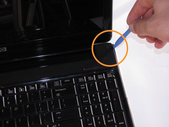
Turn the computer over, and locate the Switch Cover.
-
Using the Safe Pry Tool, un-clip the Switch Cover until it detaches from the computer.
-
-
Dieser Schritt ist noch nicht übersetzt. Hilf mit, ihn zu übersetzen!
-
Slide the Switch Cover onto the LCD Monitor, exposing the Speaker Assembly.
-
Detach the two ribbon cables from the speaker assembly.
-
-
Dieser Schritt ist noch nicht übersetzt. Hilf mit, ihn zu übersetzen!
-
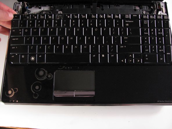
Remove the three silver Phillips 3.5mm screws that secure the keyboard to the computer.
-
Lift the rear edge of the keyboard and slide the keyboard back until the keyboard connector on the system board is accessible.
-
-
Dieser Schritt ist noch nicht übersetzt. Hilf mit, ihn zu übersetzen!
-
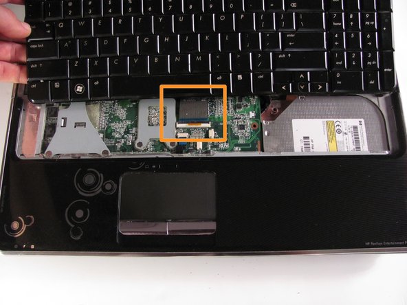
Unhinge the zero insertion force (ZIF) connector to release the ribbon cable then pull gently on the cable to release.
-
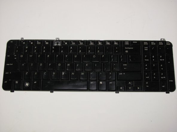
The keyboard can now be lifted off and set aside.
-
-
Dieser Schritt ist noch nicht übersetzt. Hilf mit, ihn zu übersetzen!
-
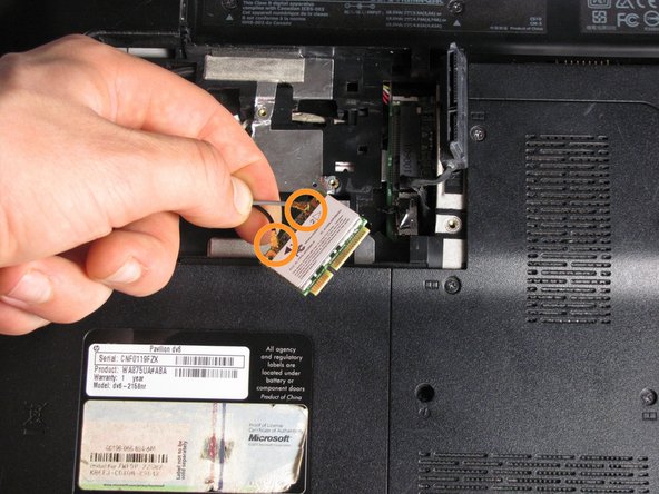
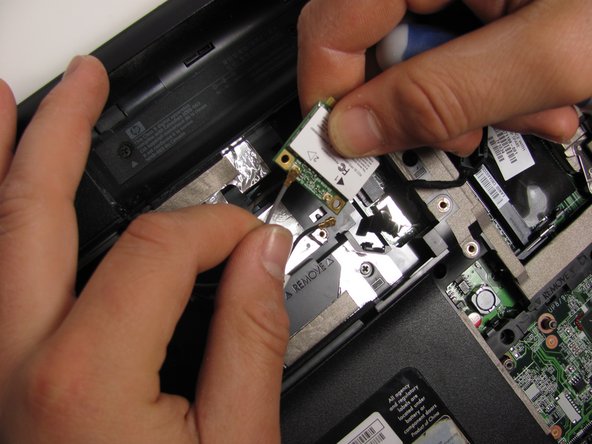
Remove the 3mm screw that secures the WLAN module to the computer. (The edge of the module opposite the slot rises away from the computer.)
-
Remove the WLAN module by pulling it away from the slot at an angle.
-
Disconnect the two WLAN antenna cables from the WLAN module.
-
-
Dieser Schritt ist noch nicht übersetzt. Hilf mit, ihn zu übersetzen!
-
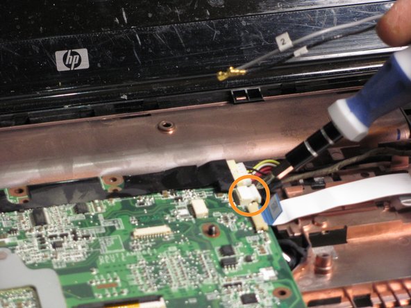
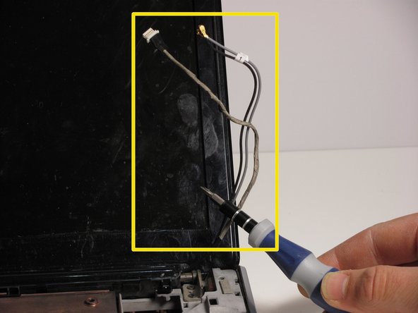
Disconnect the display panel cable by use pulling upward on cable tabs.
-
Disconnect the webcam/microphone cable from the system board.
-
Remove the WLAN antenna cables and the webcam/ microphone cable from the clips built into the top cover.
-
-
Dieser Schritt ist noch nicht übersetzt. Hilf mit, ihn zu übersetzen!
-
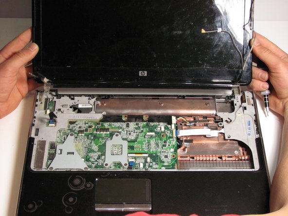
Remove the four Phillips 7mm screws that secure the display assembly to the computer.
-
Lift the display assembly straight up and remove it.
-
-
Dieser Schritt ist noch nicht übersetzt. Hilf mit, ihn zu übersetzen!
-
Remove the two Phillips 5mm screws that secure the display hinge to the display panel.
-
Use a prying tool to flex the plastic around the monitor display to release the clips holding the display case together.
-
-
Dieser Schritt ist noch nicht übersetzt. Hilf mit, ihn zu übersetzen!
-
Remove the display bezel to uncover the LCD display
-
Remove eight screws that fasten the LCD display.
-
two Phillips PM2.5×5.0 screws from the top corners.
-
six Phillips M2.5×5.0 screws from the display hinges
-
-
Dieser Schritt ist noch nicht übersetzt. Hilf mit, ihn zu übersetzen!
-
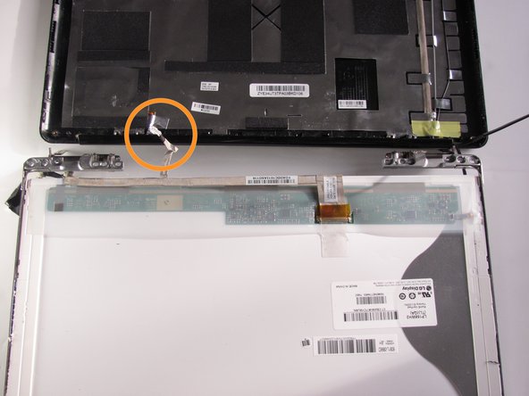
Flex the bottom of the display panel and release the display hinges
-
Place the LCD Monitor next to the display panel by flipping it over the display hinges.
-
Disconnect the display LED cable from the display panel cable and remove the display panel.
-
-
Dieser Schritt ist noch nicht übersetzt. Hilf mit, ihn zu übersetzen!
-
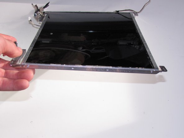
Using the Philips #1, Remove four 7mm screws from the LCD Monitor frame.
-
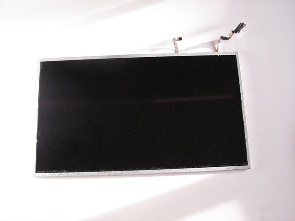
Remove the LCD Monitor from the frame.
-


Rückgängig: Ich habe diese Anleitung nicht absolviert.
8 weitere Nutzer:innen haben diese Anleitung absolviert.

Team

Cal Poly, Team 10-34, Maness Winter 2014 Mitglied von Cal Poly, Team 10-34, Maness Winter 2014
CPSU-MANESS-W14S10G34
4 Mitglieder
6 Anleitungen geschrieben