Diese Version enthält möglicherweise inkorrekte Änderungen. Wechsle zur letzten geprüften Version.
Was du brauchst
-
Dieser Schritt ist noch nicht übersetzt. Hilf mit, ihn zu übersetzen!
-
Slide the battery release latch towards you.
-
-
Dieser Schritt ist noch nicht übersetzt. Hilf mit, ihn zu übersetzen!
-
Pull up on the battery to remove it.
-
-
Dieser Schritt ist noch nicht übersetzt. Hilf mit, ihn zu übersetzen!
-
Loosen the Phillips screw labeled ‘ram’ and lift the cover.
-
-
Dieser Schritt ist noch nicht übersetzt. Hilf mit, ihn zu übersetzen!
-
Locate the green RAM card and find the metal tabs securing the card.
-
Push outwards on the two tabs to release the card.
-
-
Dieser Schritt ist noch nicht übersetzt. Hilf mit, ihn zu übersetzen!
-
Carefully slide the card out at an upward angle away from the slot.
-
-
Dieser Schritt ist noch nicht übersetzt. Hilf mit, ihn zu übersetzen!
-
Unscrew the four 8mm Philips screws marked with an icon resembling a stacks of discs.
-
Lift the cover from the right to remove it.
-
-
Dieser Schritt ist noch nicht übersetzt. Hilf mit, ihn zu übersetzen!
-
Use tweezers to detach the grey and black cables connected to the green WiFi card.
-
-
Dieser Schritt ist noch nicht übersetzt. Hilf mit, ihn zu übersetzen!
-
Remove the 8mm Philips screw located between the hard drive and the WiFi card.
-
-
Dieser Schritt ist noch nicht übersetzt. Hilf mit, ihn zu übersetzen!
-
Turn the laptop 90 degrees clockwise so you are facing the CD drive.
-
Unbend a paperclip and insert the end into the small hole by the eject button to cause the tray to pop out towards you.
-
-
Dieser Schritt ist noch nicht übersetzt. Hilf mit, ihn zu übersetzen!
-
Gently pull the tray away from the laptop and the rest of the optical drive will follow.
-
-
Dieser Schritt ist noch nicht übersetzt. Hilf mit, ihn zu übersetzen!
-
Remove the two 8mm Philips screws marked “K” on the bottom of the laptop.
-
-
Dieser Schritt ist noch nicht übersetzt. Hilf mit, ihn zu übersetzen!
-
Flip the laptop over and open the screen.
-
Push up on the four latches located at the top of the keyboard with the spudger to release them.
-
-
-
Dieser Schritt ist noch nicht übersetzt. Hilf mit, ihn zu übersetzen!
-
Lift the top of the keyboard towards you. Then, while keeping the keyboard at an angle, lift it towards the display.
-
-
Dieser Schritt ist noch nicht übersetzt. Hilf mit, ihn zu übersetzen!
-
Rotate the keyboard so that the bottom is visible.
-
With the keyboard lifted, locate the blue-striped tab on the underside of the black ribbon cable.
-
Pull the tab towards you to release the keyboard from the laptop.
-
-
Dieser Schritt ist noch nicht übersetzt. Hilf mit, ihn zu übersetzen!
-
Place the laptop face-down and rotate it 180 degrees so the vents are facing you.
-
Remove the five 8mm Philips screws. Three are on the black base and two are near the hinges.
-
-
Dieser Schritt ist noch nicht übersetzt. Hilf mit, ihn zu übersetzen!
-
Flip the laptop over.
-
Fully open the laptop.
-
-
Dieser Schritt ist noch nicht übersetzt. Hilf mit, ihn zu übersetzen!
-
Rotate it so the display is on your right and the keyboard is on your left.
-
Lift the switch cover carefully from one end while sliding the spudger between the switch cover and the laptop to separate them.
-
The switch cover should easily separate from the laptop as you run the spudger through.
-
-
Dieser Schritt ist noch nicht übersetzt. Hilf mit, ihn zu übersetzen!
-
Close the lid and rotate the laptop so that the vents are facing you.
-
Unscrew the two 8mm Philips screws below the hinges.
-
-
Dieser Schritt ist noch nicht übersetzt. Hilf mit, ihn zu übersetzen!
-
Carefully rotate the laptop 90 degrees counter-clockwise and open the screen.
-
Pull on the black tab with the HP service sticker to unplug the display from the motherboard.
-
-
Dieser Schritt ist noch nicht übersetzt. Hilf mit, ihn zu übersetzen!
-
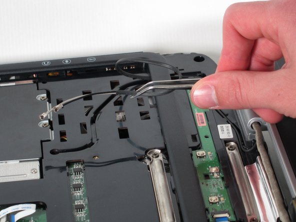
Using tweezers, remove the black cable from the hole leading to the WiFi enclosure.
-
Pull gently to remove the black and grey cables from the case.
-
-
Dieser Schritt ist noch nicht übersetzt. Hilf mit, ihn zu übersetzen!
-
Using tweezers, pull the black cable towards the display and through the hole in the casing.
-
-
Dieser Schritt ist noch nicht übersetzt. Hilf mit, ihn zu übersetzen!
-
Unscrew the two 8mm Philips screws that attach the hinge to the laptop's display.
-
Lift the screen upwards to detach it from the laptop.
-
-
Dieser Schritt ist noch nicht übersetzt. Hilf mit, ihn zu übersetzen!
-
With the laptop face-down, remove the eleven 8mm Philips screws.
-
-
Dieser Schritt ist noch nicht übersetzt. Hilf mit, ihn zu übersetzen!
-
Rotate the laptop 180 degrees so the vents are facing you.
-
Unscrew the four 3mm Philips screws below the vents.
-
-
Dieser Schritt ist noch nicht übersetzt. Hilf mit, ihn zu übersetzen!
-
Rotate the laptop 90 degrees counter-clockwise.
-
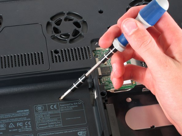
Unscrew the two 3mm Philips screws from the optical drive bay.
-
-
Dieser Schritt ist noch nicht übersetzt. Hilf mit, ihn zu übersetzen!
-
Flip the laptop over so it is face-up with the trackpad closest to you.
-
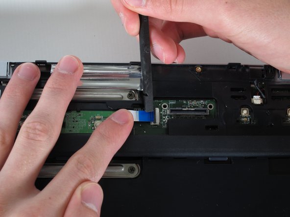
Locate the ribbon cable directly above the track pad.
-
Find the black latch at the end of the ribbon cable and unlatch it with a spudger to release it.
-
-
Dieser Schritt ist noch nicht übersetzt. Hilf mit, ihn zu übersetzen!
-
Find the ribbon cable on the LED board located at the top of the laptop.
-
You will notice that the ribbon cable is connected to two levels - you will be dealing with the one on the lower level.
-
Find the black latch at the end of the ribbon cable and unlatch it with a spudger to release it.
-
-
Dieser Schritt ist noch nicht übersetzt. Hilf mit, ihn zu übersetzen!
-
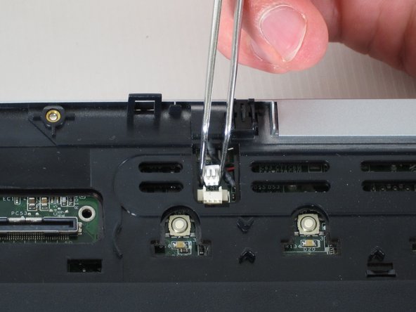
Locate the white connector attached to a red and black cable to the right of the LED board.
-
Using tweezers, pull the white connector away from you.
-
-
Dieser Schritt ist noch nicht übersetzt. Hilf mit, ihn zu übersetzen!
-
Unscrew the four 8mm Philips screws from the top cover.
-
-
Dieser Schritt ist noch nicht übersetzt. Hilf mit, ihn zu übersetzen!
-
Rotate the computer 90 degrees clockwise and insert the spudger at the seam above the card reader.
-
While lifting the front end of the top cover, slide the spudger across the seam.
-
When you have reached the firewire port, it should click open.
-
-
Dieser Schritt ist noch nicht übersetzt. Hilf mit, ihn zu übersetzen!
-
Lift the top cover from the left side to remove it completely.
-
-
Dieser Schritt ist noch nicht übersetzt. Hilf mit, ihn zu übersetzen!
-
Rotate the laptop 90 degrees counter-clockwise
-
Locate the USB Module
-
Grip the yellow cable cover and pull it to the right to release it.
-
-
Dieser Schritt ist noch nicht übersetzt. Hilf mit, ihn zu übersetzen!
-
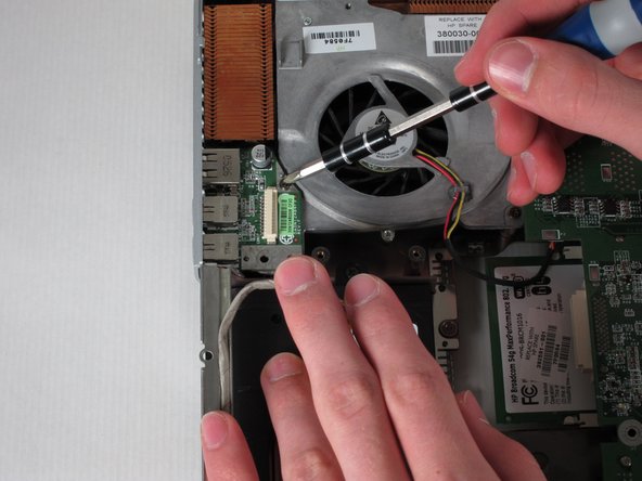
Unscrew the 6mm Philips screw connecting the USB module to the fan.
-
-
Dieser Schritt ist noch nicht übersetzt. Hilf mit, ihn zu übersetzen!
-
Pull the module to the right and lift it out to release it.
-


Rückgängig: Ich habe diese Anleitung nicht absolviert.
2 weitere Nutzer:innen haben diese Anleitung absolviert.
Team

Cal Poly, Team 24-56, Amido Spring 2011 Mitglied von Cal Poly, Team 24-56, Amido Spring 2011
CPSU-AMIDO-S11S24G56
4 Mitglieder
13 Anleitungen geschrieben