Einleitung
Use this guide to replace the motherboard.
Was du brauchst
-
-
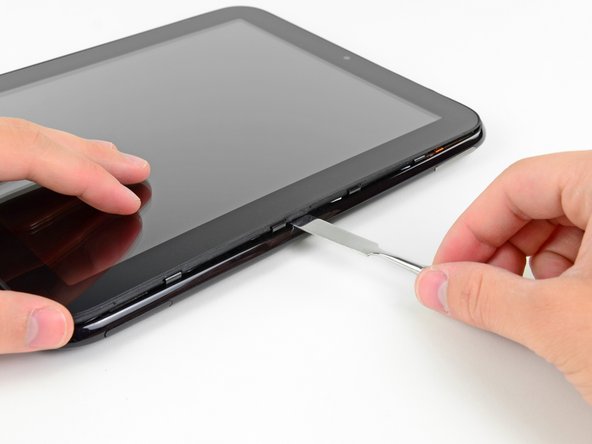
In the following steps, you will use a metal spudger to lift the front panel out from the rear case of your TouchPad.
-
-
-
Insert a flat metal spudger in the gap between the rubber outer ring on the front panel assembly and the black plastic rear case near the USB connector.
-
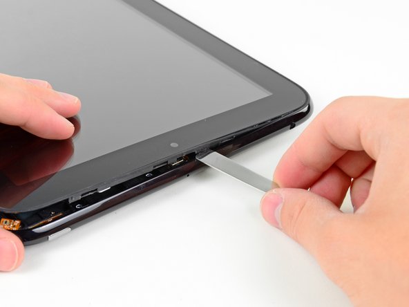
Pry the front panel assembly up from the rear case, being careful not to damage the LCD or the glass panel.
-
-
-
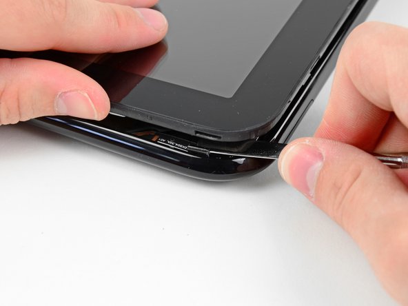
As in the previous step, use a spudger to pry the front panel up from the rear case along its long edge on the volume button side of the TouchPad.
-
Continue to pry the front panel assembly up along the volume button side of the TouchPad until there is a gap between it and the rear case.
-
-
-
Before lifting the free side of the front panel up from the rear case, you may need to release it from the plastic retaining clips holding it down.
-
Use your metal spudger to pull the stuck retaining clips away from the edge of the front panel.
-
-
-
After freeing the retaining clips, lift the front panel assembly away from the rear case.
-
-
-
Use the attached black tab to pull the display data cable straight up and out of its socket on the motherboard.
-
-
-
Use your fingernail to carefully flip up the retaining flaps on the two digitizer ribbon cable ZIF sockets.
-
Pull the digitizer ribbon cable straight out of its two sockets on the motherboard.
-
-
-
-
Use the edge of a plastic opening tool to peel up the two pieces of copper tape covering the USB connector board near the battery and the motherboard.
-
-
-
Remove the four 3.2 mm Phillips screws securing the USB connector board to the rear case.
-
-
-
Pry the upper end of the USB connector board upwards to disconnect it from its socket on the logic board.
-
-
-
Pull the USB connector board away from the bottom edge of the rear case and lift, but do not remove it out of its housing.
-
-
-
Pull the vibrator motor connector straight away from its socket on the USB connector board.
-
Remove the USB connector board from the TouchPad.
-
NOTE: First verify that there is a connector before pulling! The vibrator motor may be soldered directly to the USB Board requiring the motor to be pried up and removed together with the board.
-
-
-
Use the edge of a plastic opening tool to flip up the retaining flap on the volume control/power button ribbon cable socket.
-
Pull the cable out of its socket.
-
-
-
Use a plastic opening tool to lift the camera connector up and out of its socket on the motherboard.
-
Bend the camera cable away from the motherboard.
-
-
-
Carefully flip up the retaining flap on the microphone cable socket.
-
Pull the microphone cable out of its socket.
-
-
-
Use your plastic opening tool to pry the upper antenna connector up from its socket on the motherboard.
-
-
-
Pry up the retaining flap on the headphone jack ribbon cable socket.
-
Pull the headphone jack ribbon cable out of its socket.
-
-
-
Use a plastic opening tool to flip up the retaining flap on the digitizer board ribbon cable socket.
-
Pull the digitizer ribbon cable out of its socket.
-
-
-
De-route the lower antenna cable along the top edge of the battery and carefully pull it out from under its retaining clip near the top right corner of the battery.
-
-
-
Remove the eight 3.2 mm Phillips screws securing both the battery and the motherboard to the rear case.
-
-
-
Use a plastic opening tool to pry the battery up from the tape securing it to the rear case.
-
-
-
Lift the motherboard assembly out of the rear case, minding any cables that may get caught.
-
-
-
Carefully pull the battery away from the L-shaped motherboard to disconnect its cable.
-
Remove the battery from the motherboard.
-


To reassemble your device, follow these instructions in reverse order.
To reassemble your device, follow these instructions in reverse order.
Rückgängig: Ich habe diese Anleitung nicht absolviert.
3 weitere Personen haben diese Anleitung absolviert.
