Diese Version enthält möglicherweise inkorrekte Änderungen. Wechsle zur letzten geprüften Version.
Was du brauchst
-
-
Drehe den Laptop um.
-
Schiebe den Hebel mit dem Akkusymbol daneben fest zur Seite bis der Akku herauskommt.
-
Entferne den Akku aus dem Gerät.
-
-
-
Schiebe den rechten Hebel fest nach rechts.
-
Ziehe die Abdeckung zu dir, um sie zu entfernen.
-
-
-
Entferne die beiden 16 mm Schrauben mit einem Kreuzschlitzschraubendreher #0.
-
-
-
Drehe das Notebook so, dass die Tastatur sichtbar ist.
-
Setze den Spudger unter die linke Seite der Tastatur.
-
Hebe die Seite der Tastatur vorsichtig an, und ziehe kräftig an der linken Ecke der Tastatur, bis sie sich herauslöst.
-
Fahre jetzt mit den Fingern unter die Kanten der Tastatur von links nach rechts an der Oberkante entlang , um die restlichen Rasten zu lösen.
-
Schiebe die Taster vorsichtig nach oben in Richtung Bildschirm und entferne sie aus dem Gehäuse.
-
-
-
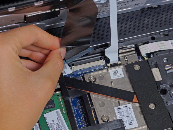
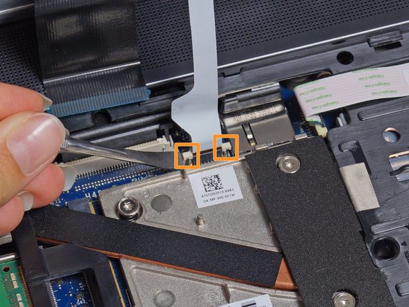
Hebe die beiden Laschen auf jeder Seite des schwarzen Flachbandkabels vorsichtig mit einem Spudger an, bis sich das Kabel löst.
-
Trenne das schwarze Flachbandkabel, indem du an der blauen Lasche ziehst, die daran hängt.
-
Wiederhole diesen Vorgang bei dem weißen Kabel.
-
-
Dieser Schritt ist noch nicht übersetzt. Hilf mit, ihn zu übersetzen!
-
Unscrew the captive screw shown near the battery compartment with a Phillips #0 screwdriver.
-
-
Dieser Schritt ist noch nicht übersetzt. Hilf mit, ihn zu übersetzen!
-
Push outward on the metal optical drive tab with a metal spudger to unlock the drive from its position in the case.
-
Once the drive is protruding from the side of the computer, pull it the rest of the way out.
-
-
-
Dieser Schritt ist noch nicht übersetzt. Hilf mit, ihn zu übersetzen!
-
Unscrew the three captive screws holding the drive in place with a Phillips #0 screwdriver.
-
-
Dieser Schritt ist noch nicht übersetzt. Hilf mit, ihn zu übersetzen!
-
Pull the green tab away from the metal casing and lift the drive out.
-
-
Dieser Schritt ist noch nicht übersetzt. Hilf mit, ihn zu übersetzen!
-
Unscrew two 3mm screws from the hard drive bay with a Phillips #0 screwdriver.
-
-
Dieser Schritt ist noch nicht übersetzt. Hilf mit, ihn zu übersetzen!
-
Remove the eight 6mm screws with a T8 Torx screwdriver.
-
-
Dieser Schritt ist noch nicht übersetzt. Hilf mit, ihn zu übersetzen!
-
Rotate the laptop so the battery compartment is in front of you.
-
Remove the four 4 mm screws under the battery with a T8 Torx screwdriver.
-
-
Dieser Schritt ist noch nicht übersetzt. Hilf mit, ihn zu übersetzen!
-
Remove three more 4mm screws from the optical drive compartment with a T8 Torx screwdriver.
-
-
Dieser Schritt ist noch nicht übersetzt. Hilf mit, ihn zu übersetzen!
-
Flip the laptop so it is keyboard side up.
-
Remove the 6mm screw with a T8 Torx screwdriver.
-
-
Dieser Schritt ist noch nicht übersetzt. Hilf mit, ihn zu übersetzen!
-
Use a spudger to lift the edges of the connector up so the white ribbon can slide out.
-
Pull the ribbons out by the blue plastic tab on the cable at each connector site.
-
-
Dieser Schritt ist noch nicht übersetzt. Hilf mit, ihn zu übersetzen!
-
Start at the front of the latop and run a plastic spudger between the top cover and the case to undo the clips holding it together
-
-
Dieser Schritt ist noch nicht übersetzt. Hilf mit, ihn zu übersetzen!
-
Angle the top cover so you can see the white ribbons shown in the picture.
-
Carefully slide the top cover toward you to expose the white ribbon connectors.
-
Use a spudger to lift the connectors and slide out both ribbons.
-
-
Dieser Schritt ist noch nicht übersetzt. Hilf mit, ihn zu übersetzen!
-
Unscrew the eight captive screws with a T9 Torx screwdriver.
-
-
Dieser Schritt ist noch nicht übersetzt. Hilf mit, ihn zu übersetzen!
-
Gently pull up on the 4 pin fan power connector cable to unplug it from the system.
-
-
Dieser Schritt ist noch nicht übersetzt. Hilf mit, ihn zu übersetzen!
-
Gently lift the fan and heatsink assembly straight up and out so you do not smear the thermal paste.
-


Rückgängig: Ich habe diese Anleitung nicht absolviert.
14 weitere Nutzer:innen haben diese Anleitung absolviert.
Team

Cal Poly, Team 8-43, Amido Winter 2015 Mitglied von Cal Poly, Team 8-43, Amido Winter 2015
CPSU-AMIDO-W15S8G43
4 Mitglieder
15 Anleitungen geschrieben
6 Kommentare
Wow, looks like that graphics card is actually user replaceable? That’s really awesome to see, with both the CPU being socketed and GPU being on a slot, that makes this system super upgradable and (hopefully) long lasting. If you manage to burn your GPU out, you don’t have to replace the entire motherboard.
I performed this procedure to replace the fan/heatsink assembly, and used the HP maintenance and service guide for this machine which can be found at http://h10032.www1.hp.com/ctg/Manual/c03... - it differs from these instructions (an improvement) is two ways - first, the optical drive should be removed before the keyboard, and then the keyboard can be pushed up from below to get it started, which is much better than forcing the whole thing from above. Secondly, removal of the top cover does not start with separating the front edge as these instructions show, but by lifting the back edge and then sliding the cover forward, which takes very little force. The Ifixit instructions were a good start, but I was glad I had the real stuff from HP.
What about electrostatic discharge though? How does it fit into the picture, and how does one protect against it?
I did this in order to clean up the innards and apply thermal paste. I gotta say it’s a hastle compared to the older EliteBooks where all you had to do to access the CPU was to open the service door/cover.
But eh, what can you do, right?
Great write up. However, these copper pipe type coolers don’t fail unless you’ve busted the fan somehow. For those of you with this overheating problem, just take it apart and put new thermal paste in there.
My 6yr old machine was overheating badly, and would BSOD on occasion. A quick look with hwinfo revealed a cpu that was hitting 100°C.
Too hot!
I blew in the vents with some light compressed air and this blew out a small slug of lint.
Didn’t help much.
Ran Aida64 FPU and it would immediately overheat and throttle
I went by the pics on here and knew that my fan was operating normally so I figured I’d try new paste before dropping $50+ on a new fan.
Pulled the heatsinks out, put some new Artic Silver on there and put it back together.
Now even under Aida64 FPU it’s only hitting 93°C now and no throttling.