Diese Version enthält möglicherweise inkorrekte Änderungen. Wechsle zur letzten geprüften Version.
Was du brauchst
-
Dieser Schritt ist noch nicht übersetzt. Hilf mit, ihn zu übersetzen!
-
Press and slide the battery cover tab to remove battery cover.
-
-
Dieser Schritt ist noch nicht übersetzt. Hilf mit, ihn zu übersetzen!
-
Pull on the black tab to lift the battery out of the battery compartment.
-
-
Dieser Schritt ist noch nicht übersetzt. Hilf mit, ihn zu übersetzen!
-
Remove the stylus by sliding it out of the slot.
-
-
Dieser Schritt ist noch nicht übersetzt. Hilf mit, ihn zu übersetzen!
-
Remove the CF card by sliding it out of the slot at the top of the device.
-
-
-
Dieser Schritt ist noch nicht übersetzt. Hilf mit, ihn zu übersetzen!
-
Press down and push the black side strips toward the top of the device to remove them.
-
-
Dieser Schritt ist noch nicht übersetzt. Hilf mit, ihn zu übersetzen!
-
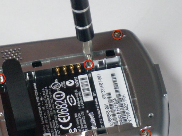
Using the T5 Torx screwdriver, remove all six screws on the back and all screws on each side of the device.
-
-
Dieser Schritt ist noch nicht übersetzt. Hilf mit, ihn zu übersetzen!
-
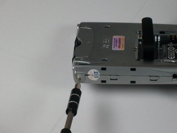
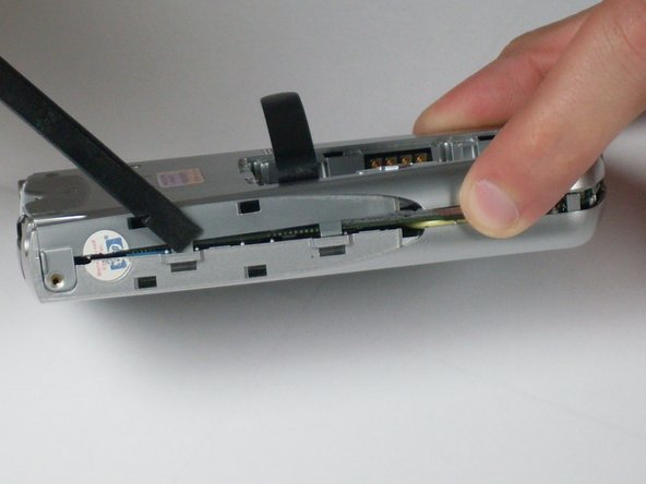
Remove the back faceplate by pushing and loosening the 4 side slots (2 on each side).
-
-
Dieser Schritt ist noch nicht übersetzt. Hilf mit, ihn zu übersetzen!
-
Open the LCD connector, where the orange strip attaches to the main board.
-
-
Dieser Schritt ist noch nicht übersetzt. Hilf mit, ihn zu übersetzen!
-
Carefully remove the orange LCD strip from the connector.
-
-
Dieser Schritt ist noch nicht übersetzt. Hilf mit, ihn zu übersetzen!
-
Unscrew the 2 screws located at each top corner of the main board.
-
-
Dieser Schritt ist noch nicht übersetzt. Hilf mit, ihn zu übersetzen!
-
Remove the main board by pushing outward on the two tabs located on each side near the bottom of the device.
-


Rückgängig: Ich habe diese Anleitung nicht absolviert.
4 weitere Nutzer:innen haben diese Anleitung absolviert.
Team

Cal Poly, Team 4-12, Forte Winter 2010 Mitglied von Cal Poly, Team 4-12, Forte Winter 2010
CPSU-FORTE-W10S4G12
3 Mitglieder
5 Anleitungen geschrieben