Diese Version enthält möglicherweise inkorrekte Änderungen. Wechsle zur letzten geprüften Version.
Was du brauchst
-
Dieser Schritt ist noch nicht übersetzt. Hilf mit, ihn zu übersetzen!
-
Remove the back of the phone by pushing firmly with your thumbs up towards the camera.
-
Remove both the battery and the SD card (Press SD card in to release)
-
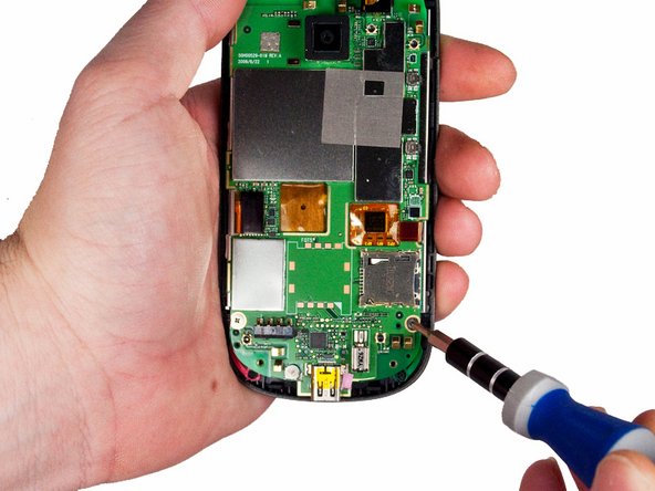
Locate and remove the four Torx screws highlighted in the photo, with the phone laying face down on your work space.
-
-
Dieser Schritt ist noch nicht übersetzt. Hilf mit, ihn zu übersetzen!
-
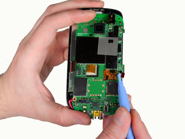
Carefully pry the inside back cover from the device using an appropriate size plastic opening tool or small flathead screwdriver.
-
Insert the flat end between the back and front enclosure, working your way around the rim.
-
-
Dieser Schritt ist noch nicht übersetzt. Hilf mit, ihn zu übersetzen!
-
Gently depress and release the small plastic tabs around the rim in the front enclosure, highlighted here.
-
-
-
Dieser Schritt ist noch nicht übersetzt. Hilf mit, ihn zu übersetzen!
-
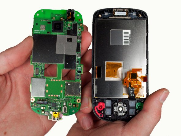
Carefully separate the front and back enclosures once all of the clips have been disengaged.
-
-
Dieser Schritt ist noch nicht übersetzt. Hilf mit, ihn zu übersetzen!
-
Remove the two screws near the bottom of the motherboard with a Phillips head screwdriver.
-
-
Dieser Schritt ist noch nicht übersetzt. Hilf mit, ihn zu übersetzen!
-
Gently pull off the ribbons holding the sides of the motherboard to the front enclosure.
-
-
Dieser Schritt ist noch nicht übersetzt. Hilf mit, ihn zu übersetzen!
-
Remove the motherboard from within the front enclosure.
-
-
Dieser Schritt ist noch nicht übersetzt. Hilf mit, ihn zu übersetzen!
-
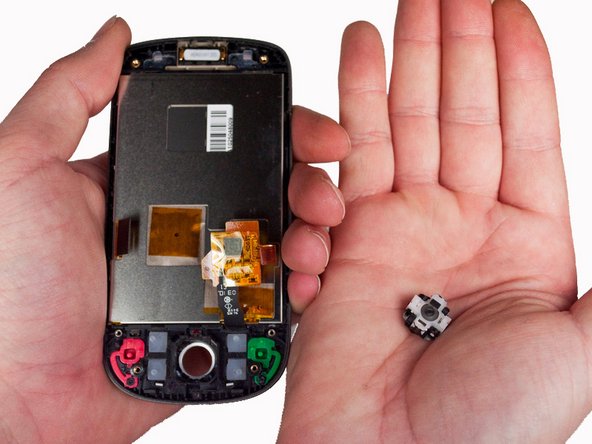
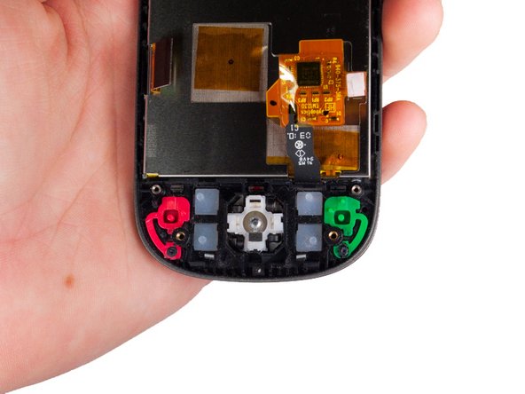
Tilt the inside of the front enclosure towards your cupped palm to remove the trackball and it's enclosure will fall out.
-
-
Dieser Schritt ist noch nicht übersetzt. Hilf mit, ihn zu übersetzen!
-
Position the phone off of the edge of the table and insert the replacement part by inserting the bevel then the trackball into the hole.
-


Rückgängig: Ich habe diese Anleitung nicht absolviert.
Ein:e weitere:r Nutzer:in hat diese Anleitung absolviert.
Team

Cal Poly, Team 3-26, Amido Winter 2012 Mitglied von Cal Poly, Team 3-26, Amido Winter 2012
CPSU-AMIDO-W12S3G26
5 Mitglieder
12 Anleitungen geschrieben